4. LS-DYNA keyword structure for pedestrian
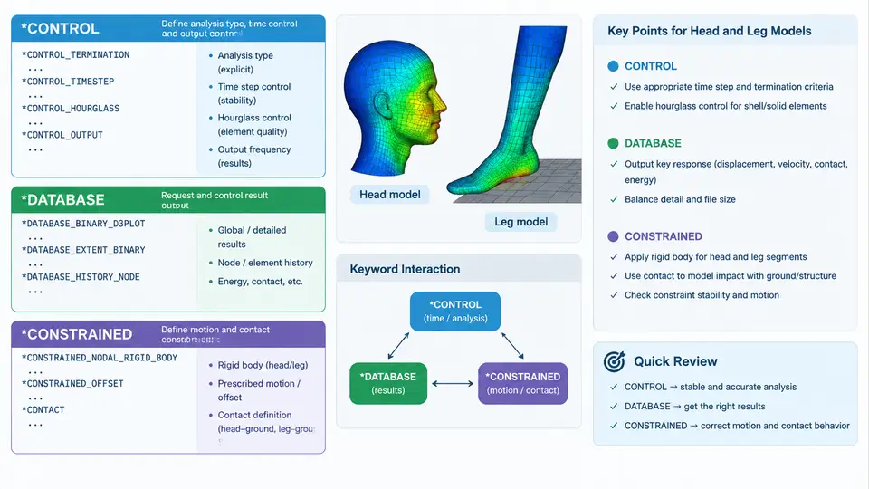
In a pedestrian head and leg impact model, the keyword deck is not a flat list of cards. It is a layered configuration system in which *CONTROL cards govern the global solver behavior, *DATABASE cards decide what physical quantities are written to disk and when, and *CONSTRAINED cards define the kinematic relationships that make the headform, legform, and vehicle body behave as a coupled mechanical system. Getting these three families right is what separates a model that merely runs from one whose output can be compared directly against Euro NCAP or GTR No. 9 acceptance criteria.
Global control: *CONTROL cards that shape the solution
The *CONTROL family sets solver-wide switches. For pedestrian impact the most consequential entries are:
*CONTROL_TERMINATION— definesENDTIM. Head impact events are short; a typical headform-to-bonnet contact lasts 10–20 ms, so anENDTIMof 0.030 s is usually sufficient, while legform tests against a bumper may need 0.040–0.060 s to capture full tibia bending and knee shear.*CONTROL_TIMESTEP— setsDTINITand, critically,TSSFAC(default 0.9). Because headform and legform meshes contain small shell elements, the stable time step is often governed by the smallest element. SettingDTINITto 0 lets LS-DYNA compute it; adding mass scaling viaDT2MSshould be done cautiously, since added mass distorts the very accelerations used for HIC and knee-bending evaluation.*CONTROL_CONTACT— controlsSLSFAC(penalty scale factor),PENOPT, andTHKOPT. For thin-shell bonnet and bumper models,THKOPT = 1activates shell thickness in contact, which prevents the headform from penetrating a panel that is only 0.7–1.2 mm thick.*CONTROL_ENERGY— enablesHGENandRWENso hourglass and rigid-wall energy are tracked. A head impact model with rising hourglass energy above roughly 5 % of internal energy is a warning sign of under-integrated shell behavior.*CONTROL_OUTPUT—NPOPTandNEECHOhelp suppress or expose echo of the input deck, useful when debugging a large pedestrian assembly.
TSSFAC at 0.9 and avoid aggressive mass scaling in head models. If the time step is too small, refine the mesh locally rather than adding mass, because HIC is directly sensitive to the acceleration history.Database cards: choosing what to measure
*DATABASE cards determine the result files. For head and leg impact the essential set is:
| Keyword | Purpose | Typical setting |
|---|---|---|
*DATABASE_BINARY_D3PLOT | Animation states for visual review | DT = 0.001 s (1 ms interval) |
*DATABASE_ASCII_GLSTAT | Global energy balance | DT = 0.0001 s |
*DATABASE_ASCII_MATSUM | Per-part energy and mass | DT = 0.0001 s |
*DATABASE_ASCII_NODOUT | Nodal acceleration for HIC | DT = 0.00005 s |
*DATABASE_ASCII_RCFORC | Contact force at interface | DT = 0.0001 s |
*DATABASE_BINARY_D3THDT | Time-history for selected nodes/elements | DT = 0.00005 s |
The sampling interval matters. HIC is computed from the resultant acceleration of the headform center of gravity, filtered according to the standard (typically CFC 1000 for head impact). If NODOUT is written at 0.1 ms, the peak acceleration can be clipped and HIC underestimated. A 0.05 ms interval is a safer default for head models. For legform tests, tibia bending moment and knee shear displacement are usually extracted from D3THDT or from a *DATABASE_HISTORY card tied to specific nodes and elements.
Constrained cards: defining the kinematic skeleton
*CONSTRAINED cards create rigid links, joints, and tied interfaces. In pedestrian models they appear in three places:
*CONSTRAINED_RIGID_BODIES— merges the headform skin, skull, and accelerometer mass into a single rigid body. This is standard for the free-motion headform, where deformation is negligible and only the resultant acceleration is of interest.*CONSTRAINED_EXTRA_NODES— attaches the accelerometer node or a reference node to the rigid headform so thatNODOUTrecords the correct point.*CONSTRAINED_JOINTor*CONSTRAINED_NODAL_RIGID_BODY— used in legform models to represent the knee joint. A revolute joint with a defined axis allows tibia rotation while transmitting shear, which is how knee bending angle is captured.
For the vehicle side, *CONSTRAINED_TIED_NODES_FAILURE is often used to bond the bumper fascia to the energy absorber. The failure plastic strain can be set so that the fascia detaches at a realistic load, preventing artificial load paths that would over-stiffen the leg impact response.
*CONSTRAINED_RIGID_BODIES on a deformable legform. The legform must bend to produce meaningful tibia and knee results; making it rigid removes the very deformation the test measures.How the three families interact in a head impact deck
The diagram below shows the data and control flow for a typical head-to-bonnet model. The *CONTROL cards set the global time and contact behavior; the headform rigid body is defined by *CONSTRAINED cards; the *DATABASE cards sample the acceleration and energy at the intervals needed for HIC and for checking hourglass growth.
Practical checks before submission
Before running a pedestrian impact deck, verify three things. First, confirm that ENDTIM is long enough for the headform to rebound and for the acceleration pulse to return to zero; a truncated pulse invalidates HIC. Second, check that NODOUT and D3THDT intervals are at least as fine as the CFC filter cutoff requires. Third, inspect the glstat file after the run: if hourglass energy exceeds about 5 % of internal energy, revisit the shell formulation or the contact thickness setting. These three checks catch the majority of keyword-level errors that would otherwise produce plausible-looking but non-compliant results.
In legform models, the same logic applies but the critical outputs shift to tibia bending moment and knee shear displacement. The *CONSTRAINED_JOINT definition must match the physical knee axis, and the *DATABASE_HISTORY card should target the elements at the tibia mid-span and the knee joint nodes. If the joint is over-constrained, the knee will not rotate and the bending moment will be artificially high; if it is under-constrained, the legform will separate. Both failure modes are visible in the d3plot animation and in the force-displacement history, so a quick visual check of the joint behavior is worth more than a long parameter sweep.