1. Course overview
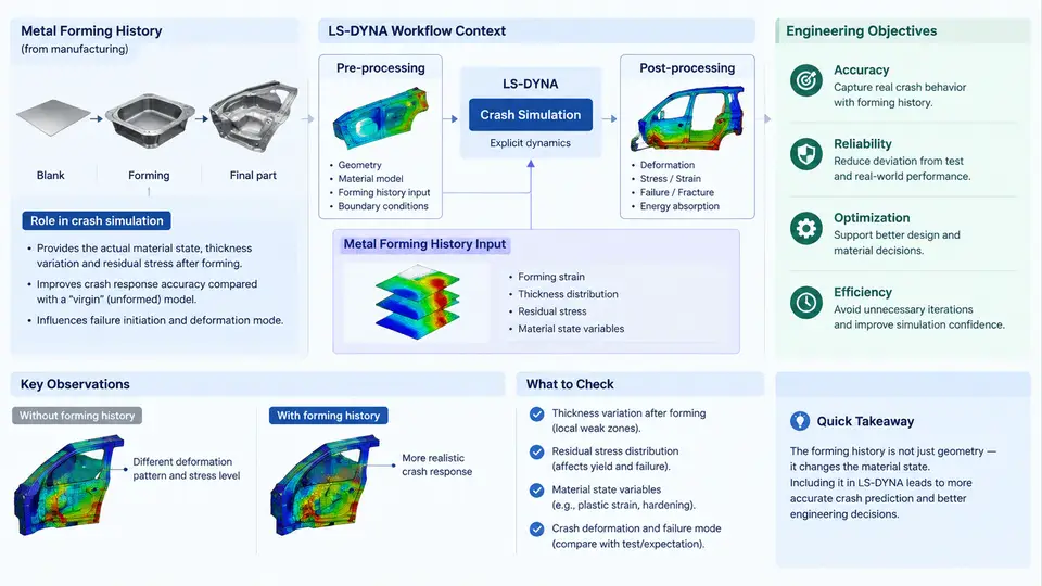
In a production vehicle, almost every structural panel and beam has already been bent, stretched, drawn, and springback-corrected before it ever reaches the body-in-white. When that same part is later subjected to a frontal or side impact, the material does not behave like a fresh, isotropic coupon. It carries a memory: thickness has thinned in some regions and thickened in others, plastic strain has accumulated along the draw direction, yield strength has shifted, and residual stress fields are locked into the geometry. Forming history is the collective name for these inherited states. Crash simulation that ignores them is, strictly speaking, simulating a part that does not exist.
This course is about capturing that memory in LS-DYNA and carrying it forward into the crash model in a way that is numerically stable, physically defensible, and practical within real project schedules. The goal is not to make every crash model a full one-step-to-crash chain, but to know when the chain is worth building, how to build it, and how to judge whether the result is trustworthy.
What "Forming History" Actually Contains
When engineers say a part has forming history, they usually mean a specific set of mapped quantities. It is worth separating them, because each one enters the crash model through a different mechanism and each has a different level of impact.
- Thickness distribution — the most visible effect. A drawn steel panel may thin by 15–25% in corners and sidewalls. Since crash energy absorption scales roughly with section area, a locally thinned section can reduce bending resistance noticeably.
- Effective plastic strain — pre-strain raises the yield point (work hardening) but consumes ductility. A region already at 0.20 effective plastic strain has far less remaining elongation before fracture.
- Residual stress — self-equilibrating stresses left after springback. These shift the local stress state and can either delay or accelerate the onset of yielding during impact.
- Material orientation and anisotropy — rolling direction and texture evolution change the directional yield response, which matters for parts loaded off-axis.
- Geometric deviation — springback and compensation mean the as-formed shape differs from the nominal CAD surface, altering initial contact and crush initiator positions.
In LS-DYNA terms, thickness and plastic strain are typically carried as element-level state (initial thickness, *INITIAL_STRESS_SHELL or mapped history variables), while residual stress is injected through initial stress definitions. Anisotropy is handled by the constitutive model itself — for example *MAT_036 (Barlat) or *MAT_037 (transversely anisotropic) — with parameters calibrated from the forming stage.
Where Forming History Sits in the LS-DYNA Workflow
The typical production chain has three stages, and forming history is the bridge between the first two and the third.
- Forming simulation — an implicit or explicit stamping analysis (LS-DYNA implicit, or a dedicated forming solver) produces the as-formed mesh with thickness, plastic strain, and stress state.
- History mapping / initialization — the formed state is transferred onto the crash mesh. This is the critical, error-prone step: the crash mesh is usually coarser and differently discretized than the forming mesh.
- Crash simulation — the mapped state becomes the initial condition for the explicit impact run.
The mapping step is where most of the engineering judgment lives. If the crash mesh is coarser, thickness and strain must be interpolated; if the meshes are topologically different, a robust projection algorithm is required. LS-DYNA provides *INCLUDE_TRANSFORM, initial stress keywords, and the INITIAL_STRESS / mapping utilities, but the quality of the transfer is the engineer's responsibility, not the solver's.
Engineering Objectives of This Course
By the end of the course, you should be able to do four things competently:
- Decide whether a given crash model needs forming history, based on part type, material, and the sensitivity of the crash metric to thickness and pre-strain.
- Execute the mapping from a forming result to a crash model, including mesh mismatch handling and keyword setup.
- Validate the mapped state — checking that thickness and strain fields are physically plausible and that the crash response changes in the expected direction.
- Diagnose common failures: negative thickness, spurious stress spikes, energy imbalance at initialization, and non-physical early fracture.
A Concrete Reference Case
Consider a B-pillar inner reinforcement made from DP780, 1.6 mm nominal thickness, formed by draw with a blank holder force of 400 kN. The forming simulation predicts a minimum thickness of 1.28 mm in the lower corner radius and a maximum effective plastic strain of 0.18 in the same region. The crash mesh uses a 5 mm target element size, while the forming mesh used 2 mm.
If the crash model is run with nominal 1.6 mm thickness everywhere, the lower corner will be artificially stiff. In a side impact, that region is a primary load path, so the model may under-predict intrusion. After mapping, the corner thickness drops to roughly 1.3 mm and the pre-strain raises local yield. The expected observable change is a softer initial slope in the force–displacement curve and slightly earlier onset of plastic hinge formation. If the mapped run instead shows a stiffer response, something in the mapping is wrong — most often a sign error in residual stress or an over-interpolated thickness field.
How the Pieces Fit Together
The diagram below shows the data flow from forming simulation through mapping into the crash model, with the key state variables carried at each stage and the main failure modes to watch for.
What You Will Be Able to Judge
The most valuable skill this course builds is not keyword memorization — it is the ability to look at a mapped crash model and decide whether the forming history was transferred correctly. That judgment rests on three questions: Is the thickness field physically plausible given the forming simulation? Is the pre-strain consistent with the material's forming limit? Does the crash response move in the direction physics predicts? If all three answers are yes, the model is defensible. If any one is no, the mapping needs to be revisited before the result is used for a design decision.
The remaining chapters build the detailed techniques — mesh mapping algorithms, keyword setup, material model selection, validation metrics, and troubleshooting — on top of this foundation. The objective throughout is the same: make the crash model represent the part that actually exists, not the part that was drawn.