4. Crash load cases and regulatory landscap
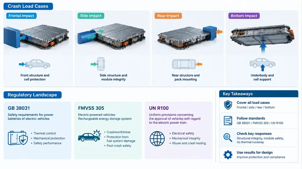
Battery pack crash protection cannot be designed against a single "worst case." A pack that survives a 50 km/h full frontal barrier may still fail in a 32 km/h side pole impact, because the two events load completely different structures through completely different paths. This chapter maps the load cases that matter for EV battery packs and the regulatory framework that defines them, so that subsequent CAE work targets the right physics rather than a generic "crash."
4.1 The Five Load Cases That Drive Pack Design
For a traction battery, five impact families dominate the design space. Each is characterized by a distinct intrusion direction, a distinct loading rate, and a distinct failure mode in the pack.
| Load case | Typical test condition | Primary pack threat | Dominant failure mode |
|---|---|---|---|
| Frontal | Full-width or 40% offset barrier, 50–64 km/h | Longitudinal crush of front rails, floor tunnel intrusion | Module compression, busbar shear, cell stack buckling |
| Side | MDB 950 kg @ 50 km/h, or pole @ 32 km/h | Lateral intrusion through rocker and door sill | Cell indentation, separator rupture, internal short |
| Rear | 70% offset MDB, 80 km/h (FMVSS 301R) | Rear rail collapse, pack rear-frame push | Connector pull-out, coolant line fracture |
| Bottom | Ground clearance strike, curb, rock, or pole | Vertical intrusion into pack underside | Bottom plate puncture, cell pouch penetration |
| Thermal runaway | Post-impact propagation test | Cell-to-cell propagation after mechanical abuse | Cascading thermal event, venting, fire |
The side impact case is usually the most demanding for a skateboard pack, because the available crush space between the rocker and the cell stack is often only 30–60 mm. In a typical 50 km/h MDB side impact, the rocker can be pushed inward by 150–250 mm before the barrier stops. If the pack's side frame and cell-to-rocker gap cannot absorb that displacement, the cells themselves become the energy absorber — which is exactly what must be avoided.
4.2 Regulatory Framework: GB 38031, FMVSS 305, and UN R100
Three regulatory families govern EV battery safety worldwide. They overlap in intent but differ in test procedure, pass criteria, and scope.
GB 38031 (China, Electric Vehicles Traction Battery Safety Requirements) is the most prescriptive for mechanical abuse. It defines a mechanical shock sequence, a vibration profile, and — critically — a thermal propagation requirement: after a single cell is triggered into thermal runaway, the occupant compartment must not catch fire for at least 5 minutes, giving passengers time to evacuate. GB 38031 also specifies a squeeze test (100 kN or 200 kN depending on revision) and a bottom-impact test using a steel hemisphere or wedge.
FMVSS 305 (US, Electric-Powered Vehicles: Electrolyte Spillage and Electrical Shock Protection) focuses on post-crash electrical safety rather than structural survival. After a frontal or side barrier impact, the standard requires that electrolyte spillage be limited and that the high-voltage system be either isolated or discharged below 60 V DC within a defined time. It does not mandate a specific intrusion limit for the pack itself.
UN R100 (UNECE Regulation No. 100, Part II) is the international baseline adopted by many markets. It requires a vibration test, a thermal shock test, a mechanical impact test, and a fire resistance test. Its mechanical impact test uses a 10 kg mass dropped or driven into the pack at a defined energy, and the pass criterion is no fire, no explosion, and no electrolyte leakage.
4.3 From Regulation to CAE Load Case Definition
Regulatory text rarely gives the CAE engineer a ready-to-run load case. The translation step is where most modeling errors originate. Consider a side-impact CAE setup for a GB 38031-aligned pack.
The regulatory side-impact condition is a 950 kg moving deformable barrier at 50 km/h striking the vehicle perpendicular to its longitudinal axis. In the model, this becomes:
*INITIAL_VELOCITY
$#  nsid        vx        vy        vz
         2      -13.89     0.0       0.0
$# 950 kg barrier, 50 km/h = 13.89 m/s in -X

*CONTACT_AUTOMATIC_SURFACE_TO_SURFACE
$#  ssid      msid      sstyp     mstyp    sboxid    mboxid       spr       fs
         3         4         2         2         0         0         0       0.3
$#   fric      dc      vc      vdc     penchk        bt        dt     bt/dt
       0.3       0.0     0.0     0.0         0       0.0       0.0       0.0
Here the barrier is a separate part set (ssid 3) with an initial velocity of −13.89 m/s along the vehicle X-axis. The contact friction coefficient of 0.3 is a reasonable starting value for steel-on-steel barrier-to-rocker contact; it should be calibrated against a physical sled test if available. The pack itself is modeled with its own mesh, and the critical output is the cell-level intrusion — not the vehicle's B-pillar intrusion, which is what a body engineer would track.
A common mistake is to model the barrier as rigid and the rocker as rigid, which eliminates the very deformation that protects the cells. In a valid model, the rocker must be able to crush, fold, and absorb energy before the load path reaches the pack side frame. If the rocker is rigid, the model will predict cell intrusion far earlier than reality.
4.4 Bottom Impact: The Under-Modeled Case
Bottom impact is the least standardized and most frequently under-modeled load case. GB 38031 specifies a bottom impact using a steel hemisphere of defined radius driven upward into the pack at a defined velocity. In CAE, this is typically a rigid sphere or wedge with an imposed velocity, contacting the bottom plate.
The key modeling decisions are:
- Bottom plate material model: aluminum bottom plates require a strain-rate-dependent plasticity model (e.g., MAT_PLASTIC_KINEMATIC with Cowper-Symonds coefficients) because the impact is fast enough to raise the flow stress by 20–40%.
- Cell representation: pouch cells can be represented as a homogenized block with a crushable foam material (MAT_CRUSHABLE_FOAM) for early-stage studies, but a detailed layered model is needed if separator rupture is the failure criterion.
- Contact: the sphere-to-plate contact must use a penalty formulation with a realistic penalty stiffness; too soft a penalty allows the sphere to "sink" into the plate and under-predicts puncture.
A practical verification check: run the bottom impact at two velocities (e.g., 10 km/h and 20 km/h) and confirm that the peak force scales roughly with the square of velocity for a rate-insensitive material, or faster if rate sensitivity is active. If the force is identical at both velocities, the material model is not capturing rate effects and the result is suspect.
4.5 Thermal Propagation as a Post-Crash Requirement
GB 38031's thermal propagation requirement is not a mechanical load case, but it is triggered by mechanical abuse. The CAE workflow is therefore two-stage: first, a mechanical impact simulation determines which cells are deformed or penetrated; second, a thermal simulation uses that cell-level damage as the trigger for a propagation study.
The handoff between the two stages is the critical engineering step. The mechanical model must output, for each cell, a damage indicator — equivalent plastic strain in the cell stack, or a penetration depth threshold. Cells exceeding the threshold are flagged as triggered. The thermal model then applies a heat generation rate to those cells and solves the propagation.
4.6 Summary of Load Case Priorities
For a typical passenger EV skateboard pack, the design priority order is: side impact (least crush space, highest cell intrusion risk), bottom impact (least standardized, highest puncture risk), frontal (longest crush zone, but high load magnitude), rear (connector and coolant integrity), and thermal propagation (post-impact consequence). The regulatory framework — GB 38031 for mechanical and thermal abuse, FMVSS 305 for post-crash electrical safety, UN R100 for international baseline — defines the minimum bar, but the CAE load cases must be derived from the regulatory text with explicit assumptions about barrier mass, velocity, contact, and material rate sensitivity. The next chapter applies these load cases to the pack-level finite element model.