1. Course overview
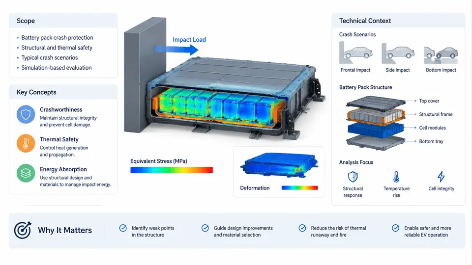
This course addresses a single, sharply defined engineering problem: how to design an electric-vehicle battery pack so that it survives crash loading without allowing the cells inside it to be mechanically damaged, electrically shorted, or thermally driven into runaway. The discipline sits at the intersection of three fields that are usually taught separately — explicit finite element analysis, automotive body structures, and lithium-ion battery safety — and the purpose of this first chapter is to establish the vocabulary, the physical picture, and the simulation workflow that every later chapter builds on.
Why the Battery Pack Is a Crash Structure
In a conventional vehicle, the occupant safety problem is dominated by the body-in-white and the restraint system. In a battery electric vehicle (BEV), the pack is not a passive payload. A typical 60–100 kWh pack weighs 400–700 kg, is 1.5–2.2 m long, and is mounted low and wide between the axles. That mass and position change the global crash pulse, the vehicle's centre of gravity, and the load paths through the floor. At the same time, the pack itself must protect hundreds of individual cells, each of which is a thin-walled metal can or pouch containing a flammable electrolyte.
The consequence is a dual requirement that defines the whole course:
- Structural requirement — the pack enclosure, its internal frames, and its mounting points must absorb and redistribute crash energy without excessive intrusion into the cell volume.
- Safety requirement — even under deformation, the cells must not be crushed beyond their mechanical limits, and no conductive path may be created between the positive and negative terminals through a deformed housing.
These two requirements are frequently in conflict. A stiff enclosure protects cells but transmits higher accelerations to the occupants and to the mounting points. A compliant enclosure absorbs energy but deforms further into the cell array. Resolving that trade-off is the central engineering activity of this course.
Core Concepts and Terminology
Before any simulation can be interpreted, a consistent set of terms is needed. The following definitions are used throughout all 30 chapters.
| Term | Definition and typical value |
|---|---|
| Cell | The smallest electrochemical unit — cylindrical (e.g. 21700), prismatic, or pouch. Nominal capacity 3–50 Ah. |
| Module | A group of cells mechanically and electrically assembled, often with a cooling plate and busbars. |
| Pack / enclosure | The complete assembly: modules, busbars, BMS, cooling circuit, and the structural housing. |
| Intrusion | Displacement of the enclosure inner surface toward the cell array, measured in mm along the impact direction. |
| Crush limit | The cell-level deformation at which internal short circuit becomes probable. For a 21700 cell this is on the order of 3–6 mm of radial indentation. |
| Thermal runaway | Self-sustaining exothermic decomposition initiated by mechanical, electrical, or thermal abuse. |
| Load path | The continuous chain of structural members through which impact force travels from the contact point to the reaction points. |
Two conventions must be fixed now because they appear in every model and every figure. First, the global coordinate system is the vehicle system: X points forward along the vehicle centreline, Y points to the left, Z points up. Second, intrusion is positive when the enclosure moves toward the cells, regardless of whether the impact comes from the side, the rear, or below. Any chapter that switches to a local coordinate system will state so explicitly.
The Simulation Workflow in Context
LS-DYNA is the industry-standard explicit solver for this class of problem because it handles large deformation, contact, self-contact, and strain-rate-dependent materials in a single transient analysis. A complete pack crash study is not one simulation; it is a sequence of models at increasing fidelity, each answering a different question.
Level 0 — Full vehicle frontal / side impact (LS-DYNA)
          → global crash pulse, pack mounting loads
Level 1 — Pack-level drop, squeeze, and pole impact
          → enclosure deformation, module displacement
Level 2 — Module-level compression and indentation
          → cell crush, busbar tearing, cooling plate rupture
Level 3 — Cell-level mechanical abuse (indentation, punch)
          → onset of internal short circuit
The critical engineering judgement is knowing which level a given question belongs to. A question about whether the pack mounting bolts shear off is a Level 0/1 question. A question about whether a specific cell short-circuits is a Level 3 question. Running a full vehicle model to answer a cell-level question is computationally wasteful and physically misleading, because the cell mesh in a full vehicle model is far too coarse to capture indentation.
How the Levels Connect: Load Transfer and Boundary Conditions
The levels are not independent. The output of one becomes the input of the next, and the quality of that transfer determines whether the whole study is meaningful. The figure below shows the data flow and the key quantities exchanged between levels.
The dashed feedback path in the figure is not decorative. In practice, a Level 3 result that shows short-circuit onset at 4 mm of indentation forces a redesign at Level 1 — a thicker enclosure wall, a different cell spacing, or an added energy-absorbing foam layer. The simulation chain is therefore iterative, and each iteration must re-run the levels above the change to confirm that the global response has not degraded.
What This Course Covers — and What It Does Not
The 30 chapters are organised into five blocks. Chapters 1–6 establish the physical and numerical foundations: pack architecture, crash load cases, material models for steel, aluminium, and foam, and the explicit time-integration scheme. Chapters 7–14 cover the modelling of the pack structure itself — enclosure meshing, spotweld and bolt representation, contact definitions, and the treatment of the cooling plate and busbars. Chapters 15–22 address the cell and module level, including homogenised cell models, detailed jelly-roll models, and the calibration of crush limits against mechanical abuse tests. Chapters 23–27 deal with validation: correlating simulation against sled and drop-tower tests, and the metrics used to judge correlation quality. Chapters 28–30 cover regulatory requirements, design optimisation, and a full worked case study.
Deliberately excluded are electrochemical and thermal-runaway propagation modelling. Those are separate disciplines with their own solvers and validation requirements. This course stops at the mechanical trigger — the moment a cell is deformed enough that an internal short becomes probable. That boundary is stated here so that no later chapter is expected to predict temperature rise or gas venting.
Reference Example: A Side Pole Impact Screening Study
To make the workflow concrete, consider a representative screening study that will be revisited in later chapters. The object is a 70 kWh pack with prismatic cells, an aluminium extrusion enclosure, and four mounting points per side. The load case is a 254 mm diameter rigid pole impacting the vehicle side at 32 km/h, aligned with the B-pillar.
The Level 0 model provides the pack mount velocity-time history. That history is applied as a prescribed motion to the Level 1 pack model, where the enclosure is meshed with shell elements and the modules are represented as homogenised solids with equivalent stiffness and density. The simulation runs for 120 ms with a mass-scaled time step. The observable output is the maximum intrusion at three monitor points along the module face. If any monitor point exceeds 5 mm, the study proceeds to Level 2 with the local deformation extracted as a boundary condition on a single module.
Typical failure symptoms at this stage are informative. If the enclosure shows almost no deformation but the mount forces are extremely high, the design is too stiff and the load is being transferred directly to the body structure. If the enclosure deforms heavily but the modules show little displacement, the cell-to-enclosure gap is absorbing the energy — which is acceptable only if the gap is intentional and the cells remain within their crush limit. If the simulation terminates early with negative volume errors, the mesh in the extrusion corners is too coarse and must be refined before any result is trusted.
These three outcomes — stiff, compliant, and numerically invalid — are the first diagnostic patterns a pack crash engineer learns to recognise. Every subsequent chapter adds detail to one part of this picture, but the overall logic remains the same: define the question, transfer the load correctly, observe the right quantity, and judge against a numeric criterion.