4. Thin-walled energy absorber baseline mod
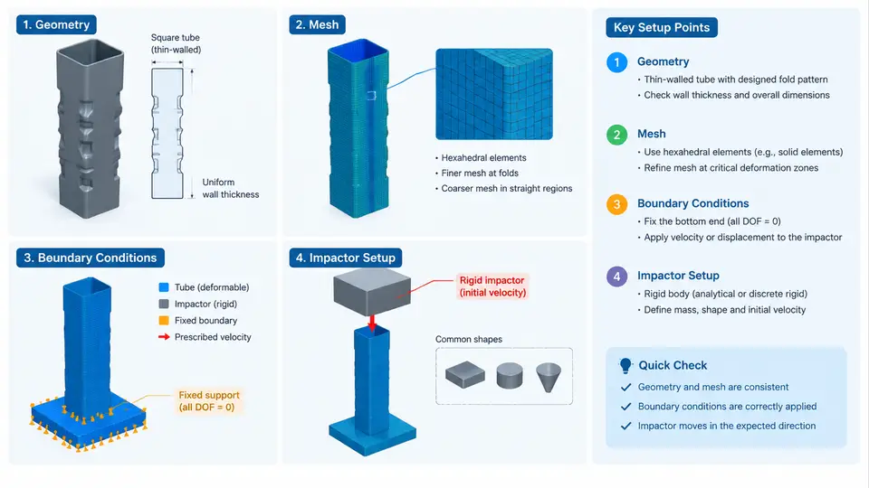
Before any multiobjective optimization can begin, the crashworthiness model must be trustworthy. In LS-DYNA, the baseline finite element model is the reference against which every design variant is compared, so its geometry, mesh, boundary conditions, and impactor definition must be deliberate rather than incidental. This section builds a complete baseline for a thin-walled energy absorber — a square-section front rail segment — and explains the reasoning behind each modeling decision.
Reference Geometry and Coordinate Convention
We adopt a right-handed global coordinate system: the X axis runs along the absorber's longitudinal (crushing) direction, Y is the lateral width, and Z is vertical. The impact load is applied along +X, so the fixed end sits at X = 0 and the struck end at X = L. This convention is used consistently in all figures and boundary definitions below.
The baseline absorber is a thin-walled square tube with the following nominal dimensions:
| Parameter | Symbol | Baseline value |
|---|---|---|
| Tube length | L | 300 mm |
| Cross-section width | b | 80 mm |
| Wall thickness | t | 2.0 mm |
| Corner radius | r | 5 mm |
| Material | — | Aluminum alloy, elastic–plastic |
| Density | ρ | 2.7e-9 tonne/mm³ |
| Young's modulus | E | 70 GPa |
| Yield stress | σy | 200 MPa |
LS-DYNA uses a consistent unit system; here we work in mm–tonne–s–N–MPa. Density must therefore be entered as 2.7e-9 tonne/mm³, not 2700 kg/m³. Mixing unit systems is one of the most common causes of a model that runs but produces nonsense energies.
Mesh Strategy for the Thin Wall
The tube wall is discretized with *SECTION_SHELL elements using the Belytschko–Tsay formulation (ELFORM = 2), which is robust for large-deformation folding. Five integration points through the thickness (NIP = 5) capture bending and membrane coupling during fold formation. A target element edge length of 4 mm is used, giving roughly 75 elements along the length and 20 around the perimeter — sufficient to resolve the half-fold wavelength of the square tube.
*SECTION_SHELL
$#   secid    elform      shrf       nip     propt   qr/irid       icomp
         1         2       1.0         5       1.0         0         0
$#    t1        t2        t3        t4
       2.0       2.0       2.0       2.0
Two mesh-quality checks matter here. First, element aspect ratio should stay below about 3:1; a 4 mm × 12 mm strip will bias fold initiation. Second, the corner radius region needs at least three elements across the arc, otherwise the corner stiffness is overestimated and the predicted peak force rises artificially. A convergence check — rerunning at 3 mm and 2 mm edge length and comparing peak force and absorbed energy — confirms whether 4 mm is adequate. If peak force changes by more than about 5%, refine further.
Material and Self-Contact
The aluminum wall uses *MAT_PLASTIC_KINEMATIC (MAT_003) with isotropic hardening, which is adequate for the baseline. Strain-rate sensitivity can be added later via the Cowper–Symonds coefficients C and P, but for a quasi-static-equivalent baseline they are set to zero.
*MAT_PLASTIC_KINEMATIC
$#     mid        ro         e        pr      sigy      etan      beta
         1   2.7e-09     70000       0.3       200       1.0       0.0
$#     src        srp        fs        vp
       0.0       0.0       0.0       0.0
Self-contact is essential: the folding walls must not pass through each other. A single-surface automatic contact handles this without needing a predefined contact surface.
*CONTACT_AUTOMATIC_SINGLE_SURFACE
$#   ssid      msid      sstyp     mstyp    sboxid    mboxid       spr       mpr
         1         0         2         0         0         0         0         0
$#     fs        fd        dc        vc       vdc        penchk        bt        dt
       0.2       0.2       0.0       0.0       0.0         0       0.0       0.0
Friction coefficients FS = FD = 0.2 are a reasonable starting point for lubricated metal-on-metal folding; they mainly affect the post-crush force plateau, not the initial peak.
Boundary Conditions
The rear end of the absorber is fully constrained to represent the vehicle body attachment. All six degrees of freedom are fixed on the node set at X = 0:
*BOUNDARY_SPC_SET
$#    nsid       cid      dofx      dofy      dofz     dofrx     dofry     dofrz
         1         0         1         1         1         1         1         1
This rigid clamp is a modeling idealization. In a real vehicle the rail is attached to a deformable structure, so the clamp slightly overestimates the constraint stiffness. For a baseline whose purpose is relative comparison across design variants, this is acceptable — but it must remain identical across all variants, otherwise the optimization compares apples to oranges.
Impactor Setup
The impactor is modeled as a rigid wall or rigid body moving along +X. Two common choices exist, and the choice affects the result interpretation:
- Rigid wall with prescribed motion (
*RIGIDWALL_PLANAR_MOVING): the wall advances at constant velocity, and the reaction force is read directly. Simple and stable. - Rigid body with initial velocity and added mass (
*MAT_RIGID+*INITIAL_VELOCITY): represents a trolley or sled with real inertia, giving a more physical deceleration history.
For the baseline we use the rigid-body approach with an initial velocity of 15 m/s and an added mass of 500 kg, representing a simplified sled. The impactor face is a 200 mm × 200 mm plate, larger than the tube cross-section so the tube is fully engaged.
*MAT_RIGID
$#     mid        ro         e        pr         n    couple         m     alias
       100   7.85e-09    210000       0.3         0         0       0.0
$#   cmo      con1      con2
       1.0         0         0

*INITIAL_VELOCITY
$#    nsid       nsidex     boxid
       100           0         0
$#    vx        vy        vz       vxr       vyr       vzr
      15.0       0.0       0.0       0.0       0.0       0.0

*ELEMENT_MASS
$#   eid       nid       mass
       1       100     5.0e-04
Note the mass unit: 500 kg = 5.0e-04 tonne in the mm–tonne–s system. The rigid body is constrained to translate only along X so that no spurious lateral drift contaminates the force signal.
t = 0. A small initial gap (0.1–0.5 mm) avoids initial penetration warnings; a large gap wastes computation time and can cause the contact to miss the first time step.
Termination and Energy Control
Set the termination time to allow full crush — for a 300 mm tube at 15 m/s, roughly 20 ms is sufficient. Enable energy reporting to verify the model:
*CONTROL_TERMINATION
$#  endtim    endcyc     dtmin    endeng    endmas
      0.020         0         0.0       0.0       0.0

*CONTROL_ENERGY
$#    hgen      rwen    slnten     rylen
         2         2         2         2

*DATABASE_GLSTAT
$#      dt    binary      lcur     ioopt
   1.0e-04         0         0         1

*DATABASE_MATSUM
$#      dt    binary      lcur     ioopt
   1.0e-04         0         0         1
After the run, check the GLSTAT file: total energy should stay nearly constant, hourglass energy should remain below 5% of internal energy, and the sliding-interface energy should be small. If hourglass energy exceeds 10%, the mesh is too coarse or the hourglass control needs stiffening.
Baseline Result and What to Verify
A correctly built baseline produces a force–displacement curve with a sharp initial peak (typically 60–90 kN for this geometry), followed by a progressive folding plateau around 25–40 kN. The key verification quantities are:
| Quantity | How to obtain | Expected baseline range |
|---|---|---|
| Peak crushing force (PCF) | Max of contact force in rcforc | 60–90 kN |
| Mean crushing force (MCF) | Absorbed energy ÷ crush distance | 25–40 kN |
| Specific energy absorption (SEA) | Energy ÷ mass | 15–25 kJ/kg |
| Crush distance | Final displacement of impactor | ≥ 150 mm |
If the tube fails to fold progressively — for example, it bends globally or the first fold forms at the clamped end — the usual causes are insufficient trigger, an over-stiff boundary, or a mesh too coarse at the corners. Adding a small geometric imperfection (a 1 mm deep dent or a reduced-thickness band near the struck end) is the standard remedy to force a stable first fold.
The baseline model is now complete and internally consistent. Every subsequent design variant in the optimization study will reuse this exact mesh topology, contact definition, boundary condition, and impactor setup, changing only the geometric parameters under study. That discipline is what makes the multiobjective comparison meaningful.