1. Crashworthiness design optimization land
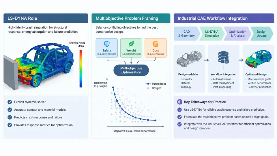
Crashworthiness design optimization sits at the intersection of three demanding disciplines: nonlinear explicit finite element analysis, multiobjective mathematical programming, and the industrial vehicle development process. LS-DYNA occupies the center of this intersection because it is the de facto solver for transient dynamic events — vehicle frontal offset impacts, side pole intrusions, pedestrian protection, battery pack crush, and occupant restraint deployment. Understanding the landscape means understanding what LS-DYNA contributes, how a crashworthiness problem is framed as a multiobjective optimization task, and where the optimization loop attaches to an existing CAE workflow.
Why LS-DYNA Anchors the Crashworthiness Loop
Crash simulation is a transient, highly nonlinear, contact-dominated problem. The explicit central-difference time integration scheme in LS-DYNA advances the solution with a critical time step governed by the smallest element characteristic length and the material wave speed:
Δt_crit = L_e / c, c = sqrt(E / ρ)For a typical steel body-in-white shell element with L_e = 5 mm, E = 210 GPa, and ρ = 7.85e-9 tonne/mm³, the wave speed is approximately 5.17e6 mm/s, giving Δt_crit ≈ 9.7e-7 s. A 120 ms frontal impact therefore requires on the order of 10⁵ time steps. This cost structure is precisely why surrogate-assisted optimization, rather than direct nested simulation, dominates industrial practice.
LS-DYNA also supplies the material and contact machinery that crashworthiness objectives depend on: *MAT_PIECEWISE_LINEAR_PLASTICITY with strain-rate scaling, *MAT_024 for mild steel, *MAT_098 or *MAT_187 for aluminum, spotweld and adhesive failure models, and *CONTACT_AUTOMATIC_SINGLE_SURFACE for self-contact during folding. The optimization variables usually act on these cards indirectly — through thickness, material grade, bead geometry, or topology — rather than on solver numerics.
Framing the Multiobjective Problem
A crashworthiness design problem is rarely a single-objective minimization. The engineer must simultaneously reduce intrusion into the occupant compartment, lower peak deceleration, control the energy absorption history, and keep mass within a program target. Formally:
minimize  F(x) = [ f1(x), f2(x), ..., fk(x) ]
subject to  g_j(x) ≤ 0,   j = 1..m
            x_lower ≤ x ≤ x_upper
Typical objectives and constraints for a frontal impact study are summarized below. The values are representative of a mid-size passenger car program and are given as illustrative targets, not measured results.
| Quantity | Symbol | Role | Illustrative target |
|---|---|---|---|
| B-pillar intrusion | f₁ | Objective (min) | ≤ 120 mm |
| Peak chest deceleration | f₂ | Objective (min) | ≤ 40 g |
| Total mass | f₃ | Objective (min) | ≤ 385 kg |
| Specific energy absorption | g₁ | Constraint | ≥ 12 kJ/kg |
| Toe pan intrusion | g₂ | Constraint | ≤ 150 mm |
Because these objectives conflict — adding gauge raises energy absorption but also mass — the solution is not a single point but a Pareto front. The designer's task is to generate a well-distributed front and then select a compromise using program priorities.
Where Optimization Attaches to the CAE Workflow
The industrial workflow is a closed loop, not a linear sequence. Geometry and mesh are prepared in a preprocessor, LS-DYNA executes the deck, a post-processor extracts responses, and an optimizer updates the design variables. The critical engineering decision is where to insert the surrogate model, because each LS-DYNA run of a full vehicle model may take 4–12 hours on 32–64 cores.
Practical Integration Considerations
Three integration issues determine whether the loop converges in a useful timeframe. First, parameterization must be solver-safe: changing a shell thickness from 1.2 mm to 1.8 mm is trivial, but moving a bead or altering a joint may require remeshing, which breaks the one-deck-per-sample assumption. Morphing tools that deform the existing mesh are preferred over CAD regeneration for this reason.
Second, response extraction must be automated and robust. Intrusion is typically read from a nodal history at a defined section cut; peak deceleration requires filtering per SAE J211 (CFC 60 for chest, CFC 180 for head). If the filter class is inconsistent between runs, the optimizer will chase noise rather than physics.
Third, constraint handling needs margin. A constraint at exactly 120 mm intrusion will produce many infeasible samples near the boundary. Setting the surrogate constraint at 115 mm and verifying against 120 mm provides a buffer against surrogate error, which for Kriging models of crash responses is commonly 5–15% RMSE.
What This Course Builds Toward
The remaining chapters develop each element of this loop in depth: design variable definition and morphing, DOE and sampling strategy, surrogate construction and validation, multiobjective algorithms, constraint handling, robustness and reliability, and finally the verification and decision-making step. The landscape described here — LS-DYNA as the physics engine, a Pareto-based multiobjective formulation, and a surrogate-assisted loop embedded in the CAE workflow — is the frame within which all subsequent techniques operate.