1. Introduction to LS-DYNA for composite ve
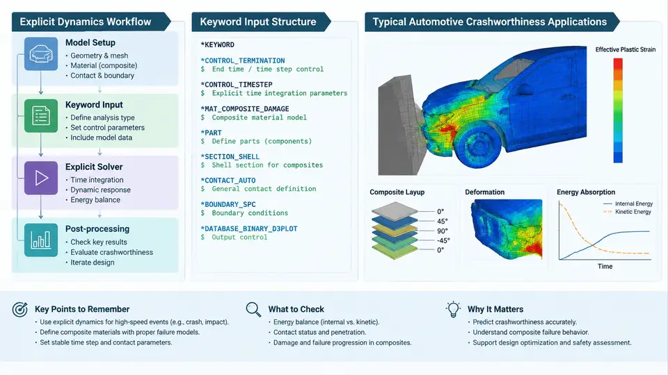
LS-DYNA is a general-purpose explicit dynamics finite element solver originally developed at Lawrence Livermore National Laboratory and now maintained by Ansys. Its core strength lies in solving highly nonlinear, transient problems involving large deformations, contact, material failure, and multi-physics coupling. For automotive crashworthiness engineering, LS-DYNA has become the de facto industry standard, and its capabilities extend naturally to composite vehicle structures—body panels, battery enclosures, crash boxes, and full vehicle models—where anisotropic material behavior and progressive damage must be captured under impact loading.
Why Explicit Dynamics for Crash Simulation
Crash events unfold over roughly 50–150 milliseconds. Within that window, sheet metal folds, composite plies delaminate, spot welds rupture, and airbags deploy. The governing equations are dynamic and highly nonlinear. An implicit solver would require assembling and inverting a global stiffness matrix at every iteration, and convergence becomes extremely difficult once contact and material failure are active. The explicit method sidesteps this by using a central difference time integration scheme: nodal accelerations are computed directly from the force balance at each node, and the solution advances without solving a system of equations.
The trade-off is conditional stability. The stable time step is governed by the Courant–Friedrichs–Lewy (CFL) condition, approximately Δt ≤ Lc/c, where Lc is the characteristic element length and c is the wave speed in the material. For a typical steel element of 5 mm with a wave speed around 5000 m/s, the stable step is on the order of 1 microsecond. A 100 ms crash event therefore requires roughly 100,000 time steps. This is why explicit crash models are computationally expensive but embarrassingly parallel—LS-DYNA scales well across hundreds or thousands of CPU cores using MPI.
The Keyword Input Structure
LS-DYNA input decks are plain-text files organized as a sequence of keyword blocks. Each block begins with an asterisk (*) followed by a keyword name, and the data lines beneath it follow a fixed-field or comma-delimited format. Understanding this structure is essential because nearly all preprocessors (LS-PrePost, ANSA, HyperMesh) ultimately write this format.
A minimal deck for a composite impact problem contains several mandatory and optional blocks:
*KEYWORD
*CONTROL_TERMINATION
$  endtim    endcyc    dtmin     endeng    endmas
   0.120               0.0
*CONTROL_TIMESTEP
$  dtinit    tssfac    isdo      tslimt    dt2ms
   0.0       0.90      0         0.0       -1.0e-6
*DATABASE_BINARY_D3PLOT
$     dt      lcdt      beam      npltc
   0.002
*PART
$  title
Composite_B_Pillar
$     pid       secid       mid       eosid
       100         200       300
*SECTION_SHELL
$  secid     elform     shrf      nip     propt
    200         2        1.0        5       1.0
*MAT_ENHANCED_COMPOSITE_DAMAGE
$     mid        ro        ea        eb        ec
      300    1.55e-9    135000     10000     10000
$     prba      gab       gbc       gca
     0.30      5000      4000      4000
$    xc        xt        yc        yt        sc
    1500      2500      200       50       120
*INTEGRATION_SHELL
$    nip       esop      failopt
      5         0.0        0.0
$  s     wf      ...
   0.0   0.125
   0.0   0.250
   0.0   0.500
   0.0   0.750
   0.0   1.000
*SET_PART_LIST
$    sid
     10
$    pid1      pid2
     100
*CONTACT_AUTOMATIC_SINGLE_SURFACE
$    ssid      msid      sstyp     mstyp
      10                 2
$     fs        fd        dc        vc
     0.20      0.20
*INITIAL_VELOCITY
$    nsid      nsidex    boxid
       1
$     vx        vy        vz
   -15000       0.0       0.0
*END
Several points deserve attention. The *CONTROL_TIMESTEP card with dt2ms = -1.0e-6 activates mass scaling: any element whose stable step falls below 1 microsecond receives added mass to raise its step. This is a common and sometimes necessary technique, but it must be used judiciously—excessive mass scaling artificially increases inertia and can mask real failure modes. The *SECTION_SHELL card with elform = 2 selects the Belytschko–Tsay shell formulation, widely used for crash applications. The *MAT_ENHANCED_COMPOSITE_DAMAGE (MAT_054/055) card defines orthotropic elastic constants, Poisson's ratios, shear moduli, and strength parameters for longitudinal and transverse directions. The *INTEGRATION_SHELL card specifies through-thickness integration points, which for a five-point rule allows the solver to track ply-by-ply stress and damage.
*PART card links a part ID to a section ID and a material ID. A common beginner error is mismatching these IDs or omitting the *SECTION definition entirely, which causes LS-DYNA to terminate with a "missing section" error during initialization.
Typical Automotive Crashworthiness Applications
Composite materials appear in modern vehicles in several crash-relevant locations. Carbon-fiber-reinforced polymer (CFRP) B-pillars and rocker panels are designed to absorb energy through progressive crushing rather than brittle fracture. Glass-fiber-reinforced thermoplastic battery enclosures must withstand intrusion without puncturing the cells. Front crash boxes made from braided composites are tuned to collapse at a controlled force level. In each case, the simulation must predict not only peak force and intrusion but also the failure sequence—delamination, fiber tensile failure, matrix cracking—because these determine whether the structure meets occupant safety targets.
A representative load case is the frontal offset deformable barrier (ODB) test at 64 km/h. The vehicle model, including composite front-end components, is impacted against a honeycomb barrier. The simulation output includes nodal acceleration histories at the B-pillar base, intrusion contours, and energy absorption curves. Engineers compare the simulated acceleration pulse against sled test data and adjust ply layup, trigger geometry, or material parameters until the correlation falls within acceptable tolerances—typically a peak force within 10% and a pulse shape within 15% of the physical test.
Workflow Overview
The explicit dynamics workflow for a composite crash simulation follows a consistent sequence: geometry preparation and meshing, material characterization and card definition, contact and boundary condition setup, initial velocity and termination control, execution via the LS-DYNA solver, and post-processing in LS-PrePost. The diagram below illustrates the data flow and the key keyword blocks associated with each stage.
The workflow is not strictly linear. After post-processing, engineers typically return to the material card or layup definition to improve correlation. This iterative loop—simulate, compare against test data, adjust, re-run—is the core of model validation. A well-correlated composite crash model can then be used for design space exploration, where ply angles, thickness distributions, and trigger geometries are varied to optimize energy absorption while minimizing mass.
Key Considerations for Composite Modeling
Composite materials introduce modeling challenges that isotropic metals do not. The material response is direction-dependent, so the local coordinate system of each shell element must align with the fiber orientation. In LS-DYNA, this is handled through the *ELEMENT_SHELL_BETA card or by defining a local coordinate system in the part definition. Failure is progressive rather than instantaneous: matrix cracking may occur at low strain, while fiber failure requires much higher strain. The MAT_054 card captures this by allowing separate failure criteria for fiber tension, fiber compression, matrix tension, and matrix compression. Once a failure criterion is met, the corresponding stiffness component is degraded, and the load is redistributed to intact plies.
Contact between composite plies and adjacent metallic structures must also be defined carefully. A single-surface contact with a friction coefficient of 0.2–0.3 is typical for composite-to-steel interfaces. For delamination modeling, cohesive zone elements or tied contact with a failure criterion may be used, though this significantly increases model size and run time.
In summary, LS-DYNA provides a mature and well-validated framework for composite vehicle impact simulation. The explicit solver handles the nonlinear transient response efficiently, the keyword input structure offers fine-grained control over material, section, and contact definitions, and the post-processing tools allow engineers to extract the metrics that matter for crashworthiness. The remainder of this course builds on this foundation, moving from material characterization and single-element validation through to full vehicle model assembly and correlation against physical test data.