1. Bumper and crash box systems in vehicle
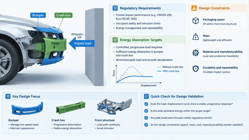
In a frontal collision, the bumper and crash box assembly is the first structural system to absorb energy before the load path reaches the longitudinal rails and the occupant compartment. Its job is not simply to "resist" impact but to manage a controlled, progressive collapse that converts kinetic energy into plastic deformation at a predictable force level. Understanding the regulatory framework, the energy targets derived from it, and the packaging constraints that limit the design space is the foundation for every subsequent decision in material selection, geometry, and simulation setup.
Regulatory Requirements and Their Physical Meaning
Two test families dominate frontal low-speed and high-speed requirements. Low-speed damageability tests — FMVSS Part 581 in the United States and the ECE R42 / RCAR bumper barrier tests in Europe and Asia — use a rigid or deformable barrier at 4 km/h to 16 km/h. Their purpose is to protect the vehicle body from costly damage, so the bumper beam and crash box must absorb the impact without permanent deformation of the rails, hood, or lighting. High-speed occupant protection tests — FMVSS 208 (full frontal rigid barrier at 56 km/h) and Euro NCAP / C-NCAP offset deformable barrier at 64 km/h with 40% overlap — instead evaluate restraint system performance and structural integrity, where the crash box contributes to the early portion of the deceleration pulse.
The distinction matters because the two regimes impose conflicting requirements. A crash box stiff enough to pass a 16 km/h RCAR test without rail damage may be too stiff to trigger controlled folding at 64 km/h, producing a sharp force spike that degrades occupant deceleration. Conversely, a soft crash box that folds smoothly at high speed may allow excessive intrusion in the low-speed test. The designer must therefore tune the force–displacement characteristic across both regimes.
Energy Absorption Targets
The energy a crash box must absorb is derived from the kinetic energy of the effective mass at the test speed. For a 1,500 kg vehicle in a 16 km/h (4.44 m/s) RCAR test, the total kinetic energy is:
E = ½ · m · v²
  = 0.5 × 1500 kg × (4.44 m/s)²
  ≈ 14.8 kJ
This energy is shared between the bumper beam, the crash boxes, and any other deformable components. A typical design target allocates 40–60% to the two crash boxes, giving roughly 3–4.5 kJ per box. For the 64 km/h ODB test, the effective energy is far larger, but the crash box only contributes during the first 50–80 mm of stroke; the remainder is handled by the rails and firewall. A representative target for the crash box in this regime is a mean crush force of 60–120 kN over a stroke of 100–150 mm, depending on vehicle mass and rail stiffness.
Design target example (illustrative, not measured): For a 1,600 kg SUV, a crash box with a 120 mm stroke and a mean crush force of 90 kN absorbs approximately 10.8 kJ per box. Two boxes plus the bumper beam cover the 16 km/h RCAR energy with margin, while the force level remains below the rail buckling threshold to avoid rail damage.
Design Constraints
The crash box operates within a tightly constrained envelope. Packaging limits its length, cross-section, and mounting orientation. The front bumper fascia, grille, and cooling module dictate the available depth, often restricting the crash box to 100–200 mm. The mounting interface to the longitudinal rail must be strong enough to transfer the crush force without tearing, yet the bolted or welded joint must not introduce a stress concentration that causes premature failure.
Material selection is another constraint. High-strength steel (DP590, DP780) and aluminum alloys (6000 or 7000 series) are common. Steel offers higher energy density and easier welding; aluminum reduces mass but requires careful attention to springback and galvanic corrosion at the rail interface. The choice affects the force–displacement curve: steel crash boxes tend to fold in a stable, symmetric mode, while aluminum extrusions may crack if the alloy or temper is not matched to the strain rate.
Finally, the crash box must be compatible with the vehicle's repair strategy. A design that absorbs energy by fracturing or by permanent deformation of the rail is unacceptable for insurance ratings. The crash box should be the sacrificial element, replaceable as a bolt-on module.
From Requirements to a Workable Design
Translating these requirements into a design starts with a target force–displacement curve. The curve should rise quickly to a plateau (the mean crush force), remain stable through the stroke, and then rise sharply at the end of stroke to engage the rail. A stable plateau is achieved by triggering the crash box with a geometric initiator — a chamfer, notch, or embossed groove — that forces the first fold at a known location. Without a trigger, the box may buckle asymmetrically, producing a force spike and reduced energy absorption.
In practice, the design loop proceeds as follows. First, define the packaging envelope from the CAD assembly: available length, cross-section, and mounting bolt pattern. Second, select a material and wall thickness that give the required mean crush force. Third, add a trigger feature and verify the folding mode using a coupon-level axial crush test or a validated LS-DYNA model. Fourth, iterate the trigger geometry and thickness until the force–displacement curve matches the target. Fifth, validate the full assembly in the 16 km/h RCAR and 64 km/h ODB load cases.
Practical check: If the crash box folds but the rail also deforms in the 16 km/h test, the crash box is too stiff or the rail gauge is too thin. If the crash box does not fold at all and the rail buckles first, the trigger is ineffective or the box is too short. Both symptoms point to a mismatch between the crash box force level and the rail's buckling resistance.
Key Parameters at a Glance
| Parameter | Typical Range | Influenced By |
|---|---|---|
| Crash box stroke | 100–150 mm | Packaging depth, rail engagement |
| Mean crush force | 60–120 kN | Material grade, wall thickness, cross-section |
| Energy per box (16 km/h RCAR) | 3–4.5 kJ | Vehicle mass, energy split strategy |
| Trigger chamfer angle | 30°–60° | Folding mode, peak force reduction |
| Material | DP590–DP780, AA6000/7000 | Mass target, joining method, cost |
The next step is to model these components in LS-DYNA with appropriate material cards, contact definitions, and boundary conditions that reproduce the barrier tests. The accuracy of that model depends directly on how well the force–displacement targets and constraints described here are captured in the input deck.