1. Automotive spot weld fundamentals
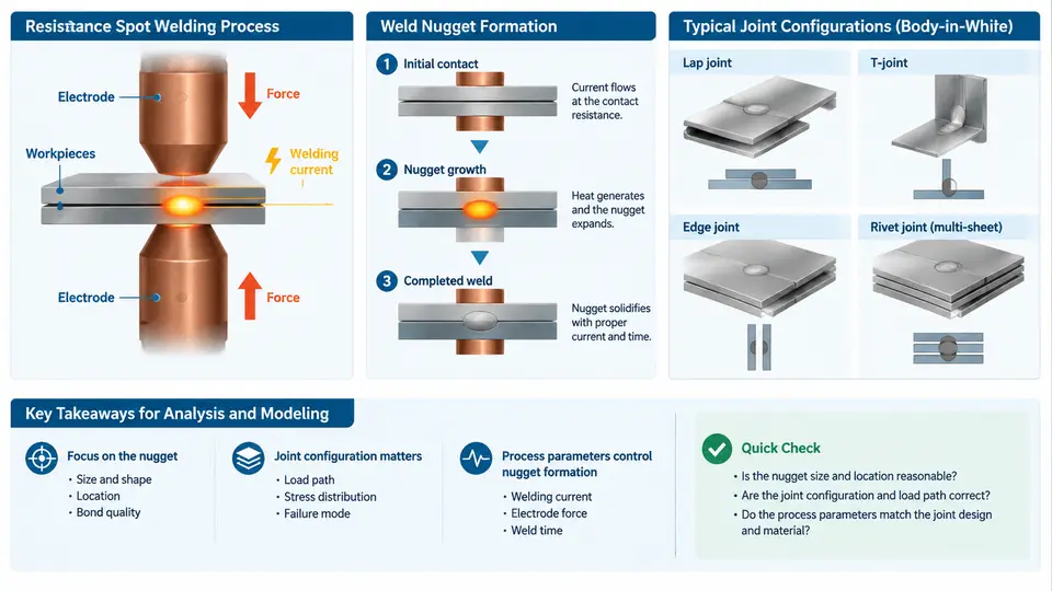
Resistance spot welding (RSW) is the dominant joining process in body-in-white (BIW) assembly. A typical steel-intensive passenger car body contains between 3,000 and 5,000 spot welds, and the structural integrity of the safety cage—B-pillars, rockers, roof rails, and shock towers—depends on the quality of these small, localized joints. For crash simulation engineers, understanding how a spot weld is physically created is not academic background; it directly determines how the joint must be modeled in LS-DYNA, which failure criterion is appropriate, and what mesh resolution is required around the weld.
The Resistance Spot Welding Process
RSW is a thermo-electro-mechanical process. Two water-cooled copper alloy electrodes clamp overlapping metal sheets under a controlled electrode force, and a high current (typically 4–12 kA for automotive steel) is passed through the stack for a short duration (roughly 100–400 ms). Joule heating at the faying interface—the contact surface between the sheets—raises the local temperature above the melting point of the steel (approximately 1,500 °C), forming a molten pool. When the current is switched off, the copper electrodes act as heat sinks and rapidly quench the pool, producing a cast nugget surrounded by a heat-affected zone (HAZ).
The process follows a characteristic sequence: squeeze, weld, hold, and off. During squeeze, the electrodes establish electrical and mechanical contact. During weld, current flows and the nugget grows. During hold, the electrode force is maintained while the nugget solidifies under pressure, preventing shrinkage porosity and expulsion. The final nugget diameter is the single most important quality metric; for a 1.0 mm sheet, a minimum acceptable nugget diameter is often specified as 4√t ≈ 4.0 mm, following common automotive standards.
Weld Nugget Formation and Microstructure
The nugget is not a homogeneous cylinder. It consists of a cast zone with a dendritic solidification structure, bounded by a HAZ where the base metal has been heated but not melted. The HAZ exhibits grain growth and, in high-strength steels, may contain tempered or softened regions. This microstructural gradient matters for simulation because failure can initiate in the HAZ rather than at the nugget-sheet interface, particularly under peel or combined loading.
Nugget growth is governed by the interaction of electrical resistance and thermal diffusion. Contact resistance at the faying surface is initially high, promoting rapid heating; as the nugget forms, resistance drops and the current path widens. If current is too high or hold time too short, molten metal may be expelled—an expulsion event that reduces nugget size and creates a surface defect. In production, weld quality is monitored through process parameters and periodic destructive testing (chisel or peel tests, macro-sectioning).
Typical Joint Configurations in BIW Structures
Spot welds rarely exist in isolation. In a BIW, they appear in specific configurations dictated by the geometry of the assembly:
- Two-sheet lap joint: The most common configuration. Two overlapping sheets are welded through both. The load path is eccentric, producing rotation under tensile loading.
- Three-sheet stack-up: Common at rockers and pillars where an outer panel, reinforcement, and inner panel are joined. The nugget must penetrate the faying interface between the two inner sheets, which requires higher current or longer weld time.
- Sheet-to-thick-section joint: A thin outer panel welded to a thicker reinforcement or extrusion. The thickness ratio affects heat balance and nugget symmetry.
- Weld-to-flange edge distance: The nugget must be placed far enough from the sheet edge to avoid edge expulsion; a minimum edge distance of approximately 1.5 times the nugget diameter is a common guideline.
In crash-critical regions, welds are often arranged in lines or arrays along flanges. The spacing between welds (pitch) influences load distribution: closely spaced welds share load more evenly but increase shunt effects during welding, while widely spaced welds concentrate stress at individual joints. A typical flange pitch is 25–50 mm.
From Physical Weld to Simulation Model
LS-DYNA does not simulate the RSW process itself in a crash model. Instead, the physical nugget is represented by a simplified joint model—most commonly a beam or solid element connecting the sheets at the weld location. The choice of model depends on what the simulation must capture: a beam element with a failure criterion is efficient for full-vehicle crash, while a detailed solid nugget model may be used for local joint behavior studies.
The key takeaway is that the physical characteristics described above—nugget diameter, sheet thickness, stack-up, and HAZ—map directly to model parameters. Nugget diameter defines the beam cross-section or the solid element footprint. Sheet thickness and stack-up determine the connected nodes and the effective length of the joint. The HAZ, if modeled explicitly, requires a refined mesh and a material model that accounts for softening.
Practical Implications for Joint Modeling
When building a spot weld model in LS-DYNA, the physical details above translate into specific modeling decisions. The nugget diameter d determines the cross-sectional area of a beam element or the size of a solid element cluster. The sheet thicknesses t₁ and t₂ define the distance between the connected nodes and influence the bending stiffness of the joint. The stack-up configuration dictates whether a two-node beam (one node per sheet) or a multi-node constraint is required.
For a typical two-sheet lap joint with t₁ = 0.8 mm and t₂ = 1.2 mm, a common modeling approach uses a single beam element with a circular cross-section of diameter equal to the nugget diameter (e.g., 5 mm). The beam is connected to the mid-surface nodes of the shell elements representing each sheet. The failure criterion—whether force-based, displacement-based, or a combination—must be calibrated against physical tests such as lap-shear and coach-peel coupons.
Understanding the RSW process also helps diagnose simulation anomalies. If a model predicts weld failure at loads well below the expected joint strength, the cause may be an incorrect nugget diameter, an unrealistic failure criterion, or a mesh that is too coarse around the weld. Conversely, if welds never fail in a simulation that should exhibit joint separation, the failure criterion may be too lenient or the beam element may be over-constrained. These diagnostics require the engineer to reason from the physical process—nugget formation, HAZ properties, and load transfer—rather than treating the weld as a generic connector.
In the chapters that follow, these fundamentals will be extended into specific modeling techniques: beam and solid element representations, failure criteria calibration, mesh sensitivity, and the treatment of weld arrays under crash loading. The goal is to build models that are not only numerically stable but physically faithful to the joints they represent.