1. Automotive seat structure impact simulat
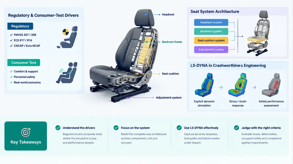
An automotive seat is not a piece of furniture. In a crash, it is a structural safety system that must hold the occupant in a controlled posture, transfer belt and occupant loads into the body-in-white (BIW), absorb energy without collapsing, and keep the occupant away from hard interior surfaces. Seat structure impact simulation is the discipline of predicting those behaviours numerically, before a single prototype is built. This chapter defines what that simulation covers, what forces drive it, how a seat system is architected, and where LS-DYNA fits in the crashworthiness engineering workflow.
1.1 What "Seat Structure Impact Simulation" Actually Covers
The scope is broader than "run a frontal sled." A complete seat impact simulation programme typically spans four load cases, each with a different physical mechanism and a different failure mode:
- Frontal impact (sled or full-vehicle): the occupant is restrained by the belt; the seat must survive belt anchorage loads, prevent excessive forward rotation of the seatback, and avoid recliner or track release. The dominant seat loads are bending moments at the recliner and shear at the track anchors.
- Rear impact (ECE R17 / FMVSS 207/202a style): the seatback is loaded rearward by the occupant's torso. The critical responses are seatback strength, head-restraint geometry, and the energy absorbed by controlled deformation.
- Lap-belt-only or misuse loading: belt routed over the seat cushion or a single anchorage point, producing localised crushing of the cushion frame and high stress at the track.
- Occupant out-of-position (OOP) and airbag interaction: the seat structure must not introduce a hard contact path that changes the occupant's kinematics.
Each case is a nonlinear, large-deformation, contact-dominated problem. That is precisely why explicit finite element analysis (FEA) — and LS-DYNA in particular — is the standard tool rather than implicit solvers.
1.2 Regulatory and Consumer-Test Drivers
Simulation requirements are not invented by CAE engineers; they are derived from the test matrix the vehicle must pass. The main drivers are:
| Driver | Typical requirement | What it forces in the seat model |
|---|---|---|
| FMVSS 207 | Seat anchorage strength, static load | Rigid anchor representation, strength check at track and recliner |
| FMVSS 202a | Head restraint height and backset | Head-restraint geometry and seatback stiffness |
| ECE R17 | Seat strength and rearward energy absorption | Seatback deformation and energy curve |
| Euro NCAP / C-NCAP | Whiplash (rear) and frontal occupant scores | BioRID / Hybrid III dummy models, seat-occupant contact |
| OEM internal targets | No structural failure, no belt slip, HIC/neck limits | Full seat + belt + dummy + BIW sub-model |
The practical consequence: the seat model must be built to the same boundary conditions as the physical test. If the sled test anchors the seat to a rigid fixture, the CAE model must use a rigid fixture, not a flexible BIW floor. Mismatched boundary conditions are one of the most common reasons a simulation "passes" while the test fails.
1.3 Seat System Architecture
A modern seat is a hierarchy of subsystems, and each one has a distinct role in impact:
- Seat frame: cushion frame and seatback frame, usually stamped steel or welded tube. Carries the primary bending and shear loads.
- Recliner mechanism: the hinge between cushion and seatback. The single most critical component in rearward loading; its locking strength often governs the design.
- Track and riser: the interface to the floor. Transfers all occupant and belt loads into the BIW. Failure here is catastrophic.
- Cushion and foam: controls occupant penetration and pressure distribution; also affects belt geometry.
- Head restraint: limits head rearward travel; its position and stiffness drive whiplash metrics.
- Trim and plastic covers: usually non-structural, but can create hard contact points in OOP cases.
In simulation, the frame, recliner, and track are modelled as deformable shells and solids; foam is modelled with a crushable foam material; trim is often simplified or omitted unless it affects contact.
1.4 Where LS-DYNA Fits
LS-DYNA is an explicit, nonlinear dynamic solver. Its core strengths map directly onto seat impact problems:
- Explicit time integration handles the large deformations and contact changes of a crash without convergence failures.
- Rich material library —
*MAT_PIECEWISE_LINEAR_PLASTICITY,*MAT_024,*MAT_CRUSHABLE_FOAM,*MAT_RIGID— covers steel, foam, and rigid fixtures. - Contact algorithms (
*CONTACT_AUTOMATIC_SINGLE_SURFACE,*CONTACT_AUTOMATIC_SURFACE_TO_SURFACE) handle seat-to-dummy, seat-to-belt, and self-contact of collapsing frames. - Belt and dummy models —
*MAT_SEATBELT,*ELEMENT_SEATBELT, and validated Hybrid III / BioRID dummies — allow occupant-restraint interaction to be simulated directly. - Implicit and explicit coupling allows a static preload (belt tension, occupant settling) to be followed by an explicit impact event.
*INCLUDE
  seat_frame.k        ! shell/solid mesh, *MAT_024
  recliner.k          ! solid mesh, high-strength steel
  track_riser.k       ! shell mesh, *MAT_024
  foam_cushion.k      ! *MAT_CRUSHABLE_FOAM
  dummy_hybrid3.k     ! validated occupant model
  belt_geometry.k     ! *ELEMENT_SEATBELT + *MAT_SEATBELT
  biw_fixture.k       ! *MAT_RIGID, boundary condition
*CONTACT_AUTOMATIC_SURFACE_TO_SURFACE
  dummy_seat
*CONTACT_AUTOMATIC_SINGLE_SURFACE
  seat_self
*CONTROL_TERMINATION
  0.120               ! 120 ms event
1.5 The Engineering Workflow Around the Solver
LS-DYNA is one step in a longer loop. A realistic seat impact CAE workflow is:
- Define the load case from the test specification: impact velocity, pulse, belt configuration, dummy type, and pass/fail criteria.
- Build or inherit the seat model — mesh quality, material cards, and connections (spot welds, bolts, adhesives) must match the physical seat.
- Set up the occupant and restraint — position the dummy, route the belt, apply pretension and initial tension.
- Run the explicit solve and monitor energy balance, hourglass energy, and contact penetration.
- Post-process — seatback rotation angle, track displacement, recliner load, dummy injury metrics (HIC, neck, chest deflection).
- Correlate with test — compare force-displacement curves and deformation modes; update the model where it diverges.
The correlation step is where the engineering value is realised. A model that has never been validated against a physical sled test is a hypothesis, not a prediction.
1.6 A Concrete Example: Rearward Seatback Loading
Consider a rear-impact sled case. The seat is anchored to a rigid fixture, a BioRID dummy is seated, and the sled pulse is a 20 g, 50 ms triangular pulse. The simulation goal is to confirm that the seatback does not rotate beyond a target angle and that the recliner does not unlock.
Key inputs: seatback frame material *MAT_024 with a yield stress of 340 MPa, recliner modelled as a solid with a locking feature represented by a contact pair, and the dummy positioned with a 40 mm backset. The observable outputs are the seatback rotation angle versus time, the recliner reaction moment, and the head-to-head-restraint gap. If the rotation exceeds the target, the engineer increases the seatback frame gauge or adds a reinforcement; if the recliner moment spikes, the locking geometry is revised. This is the loop that LS-DYNA enables — fast enough to iterate, detailed enough to be trusted.
1.7 What This Course Will Build
The remaining chapters follow the workflow above in detail: mesh and connection modelling, material card selection for steel and foam, recliner and track representation, belt and dummy setup, contact definition, solver controls, energy diagnostics, post-processing, and correlation. The goal is not to memorise LS-DYNA keywords but to understand why each modelling decision changes the predicted crash response — and how to tell when a result is trustworthy.