1. Seatbelt system fundamentals
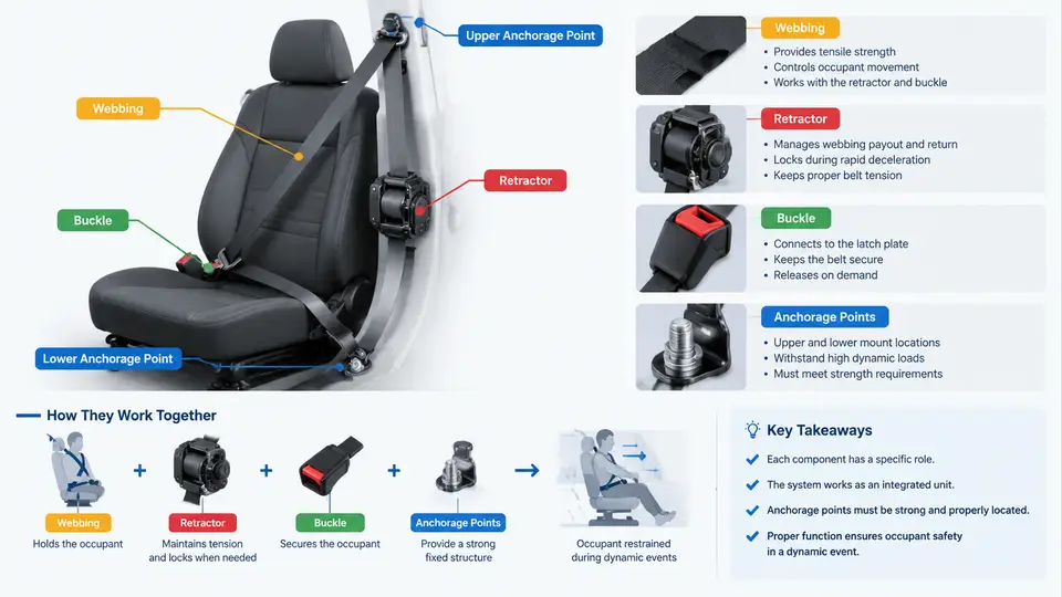
A seatbelt system is not a single device but a coordinated restraint assembly. During a dynamic event—a frontal impact, a side impact, or a rollover—each component performs a distinct function within milliseconds, and the system only works when those functions are properly sequenced. This chapter establishes the vocabulary and functional relationships that the rest of the course builds on: webbing, retractor, buckle, anchorage points, and the occupant load path that connects them.
The Restraint Load Path
The fundamental principle of seatbelt restraint is that the occupant's kinetic energy must be transferred to the vehicle structure through a controlled path. That path runs from the occupant's body, through the webbing, into the anchorage points, and finally into the vehicle body structure. Every component in this chain has a defined role:
- Webbing — the flexible tension member that contacts the occupant and distributes restraint force over a broad area of the torso and pelvis.
- Retractor — the spooling and locking device that manages webbing length, provides comfort in normal driving, and locks during a dynamic event to prevent webbing payout.
- Buckle and latch plate — the coupling that connects the occupant-side webbing to the anchorage-side webbing and allows the occupant to enter and exit the restraint.
- Anchorage points — the structural attachment locations (floor, B-pillar, seat frame) that transmit restraint loads into the vehicle body.
- Pretensioner and load limiter — supplementary devices that remove slack and control peak force, respectively, during the early phase of a crash.
The load path is only as strong as its weakest link. A retractor that locks correctly but an anchorage that deforms plastically will still allow excessive occupant excursion. This is why dynamic performance testing evaluates the complete system, not individual components in isolation.
Webbing: The Occupant Interface
Seatbelt webbing is typically woven from high-tenacity polyester yarn. The weave pattern and yarn density determine the webbing's tensile strength, elongation characteristics, and abrasion resistance. Standard webbing for passenger vehicles is approximately 46–50 mm wide and is rated for a minimum breaking strength in the range of 26–30 kN, depending on the specification and region.
Webbing elongation is a critical parameter. Some elongation is desirable because it absorbs energy and reduces peak force on the occupant. However, excessive elongation allows greater forward excursion, which increases the risk of contact with interior surfaces. The webbing's force–elongation curve is therefore a design trade-off between occupant deceleration and excursion distance.
Webbing also carries the load from the retractor to the buckle and from the buckle to the anchorage. In a three-point system, the diagonal webbing section restrains the upper torso while the lap section restrains the pelvis. The transition point—where the webbing passes through the latch plate or D-ring—is a high-stress region that must be evaluated for abrasion and cut resistance.
Retractor: Locking and Spooling
The retractor serves two functions: it stores webbing when not in use and locks the webbing during a dynamic event. Modern retractors use an emergency locking retractor (ELR) mechanism, which locks in response to either vehicle deceleration (via a pendulum or ball-in-cage inertia sensor) or rapid webbing extraction (via a centrifugal clutch on the spool).
The locking threshold is a key performance parameter. A typical ELR locks when vehicle deceleration exceeds approximately 0.45 g or when webbing acceleration exceeds approximately 1.0 g. These thresholds are calibrated to allow normal occupant movement during driving while ensuring lock-up early in a crash event.
Some retractors also include a switchable ELR/ALR (automatic locking retractor) mode. In ALR mode, the retractor locks continuously once webbing is fully extracted, which is used for child seat installation. The mode is typically switched by pulling the webbing to its full extent and allowing it to retract slightly.
Retractor performance during a dynamic event is evaluated by measuring webbing payout under load. A retractor that locks but allows excessive payout—due to spool deformation or locking pawl engagement delay—will permit greater occupant excursion than the design intends.
Buckle and Latch Plate
The buckle is the release mechanism that the occupant operates. It must withstand the full restraint load without releasing, yet open reliably with a single hand motion after the event. The latch plate is the tongue that inserts into the buckle and is attached to the webbing.
Buckle strength is typically specified as a minimum load-carrying capacity, often in the range of 15–20 kN for the buckle–latch plate assembly. The release force must remain within a narrow band—typically 40–90 N—to ensure that the buckle can be opened by a wide range of occupants, including those with limited hand strength, while not opening inadvertently during a crash.
The buckle–latch plate interface is also a potential source of false latching. A partial insertion may feel secure but release under load. Dynamic testing includes verification that the buckle remains latched under the specified load profile and that release force remains within specification after the event.
Anchorage Points and Structural Integration
Anchorage points are the physical attachment locations where the seatbelt system transfers load to the vehicle structure. In a typical three-point system, there are three primary anchorages:
- Floor anchorage — attaches the lap webbing and buckle stalk to the floor or seat frame.
- B-pillar anchorage — attaches the D-ring or height adjuster that guides the diagonal webbing.
- Retractor anchorage — attaches the retractor to the B-pillar or seat frame.
Each anchorage must withstand the full restraint load without permanent deformation or separation. The surrounding structure—the sheet metal, reinforcement plates, and weld nuts—must also be evaluated, because anchorage failure often occurs in the surrounding structure rather than in the anchorage itself.
Anchorage strength requirements are defined by regulation and by vehicle manufacturer specifications. A common requirement is that each anchorage must withstand a specified load—often 13–15 kN for the lap and diagonal anchorages—without failure. The load is applied through a test fixture that simulates the webbing geometry and direction of pull during a crash.
Pretensioners and Load Limiters
Pretensioners and load limiters are supplementary devices that improve restraint performance beyond what the basic webbing–retractor–buckle–anchorage system can achieve alone.
A pretensioner removes slack from the webbing at the very beginning of a crash event, typically within 10–20 ms of impact detection. This ensures that the occupant begins decelerating as early as possible and reduces forward excursion. Pretensioners may be pyrotechnic (using a small gas generator) or mechanical (using a spring or motor).
A load limiter allows controlled webbing payout after the pretensioner has fired, which reduces peak force on the occupant's chest. This is particularly important for smaller occupants, who are more vulnerable to chest injury from high restraint forces. The load limiter is typically integrated into the retractor or the buckle stalk and may use a torsion bar, a tearing stitch, or a friction mechanism.
The combination of pretensioner and load limiter creates a force–time profile that is optimized for occupant protection: rapid slack removal, followed by controlled force limiting. This profile is verified during dynamic sled testing, where the occupant's kinematics and the restraint forces are measured.
System Integration and Dynamic Behavior
The components described above do not operate independently. During a dynamic event, the sequence is approximately as follows:
- The crash sensor detects deceleration and sends a signal to the restraint control module.
- The retractor locks, preventing further webbing payout.
- The pretensioner fires, removing slack from the webbing.
- The occupant loads the webbing, which transfers force to the buckle, anchorages, and vehicle structure.
- The load limiter allows controlled payout, reducing peak force.
- The occupant decelerates over a controlled distance, reducing injury risk.
Each step must occur within a narrow time window. A delay in retractor locking or pretensioner firing can allow excessive occupant excursion. A load limiter that allows too much payout can allow the occupant to contact the steering wheel or dashboard. The system is tuned as a whole, and dynamic testing evaluates the complete assembly under representative crash conditions.
Practical Example: Verifying Component Roles Through a Sled Test
Consider a frontal sled test configured to evaluate a three-point seatbelt system. The test input is a deceleration pulse of approximately 30 g peak, with a duration of about 80 ms. The occupant is a Hybrid III 50th percentile male ATD (anthropomorphic test device).
The observable outputs include:
- Retractor payout — measured by a rotary potentiometer on the spool. Expected: less than 50 mm after lock-up.
- Buckle load — measured by a load cell in the buckle stalk. Expected: peak force in the range of 8–12 kN, depending on load limiter calibration.
- Anchorage displacement — measured by displacement transducers at each anchorage. Expected: less than 10 mm permanent deformation.
- Occupant kinematics — measured by accelerometers and high-speed video. Expected: forward excursion less than 300 mm for the head, with no hard contact with the steering wheel.
If the retractor payout exceeds the limit, the likely cause is a locking pawl engagement delay or spool deformation. If the buckle load is too high, the load limiter may be incorrectly calibrated or the pretensioner may have fired too late. If anchorage displacement is excessive, the surrounding sheet metal may require reinforcement. These are the diagnostic relationships that dynamic testing is designed to reveal.