1. Occupant safety testing overview
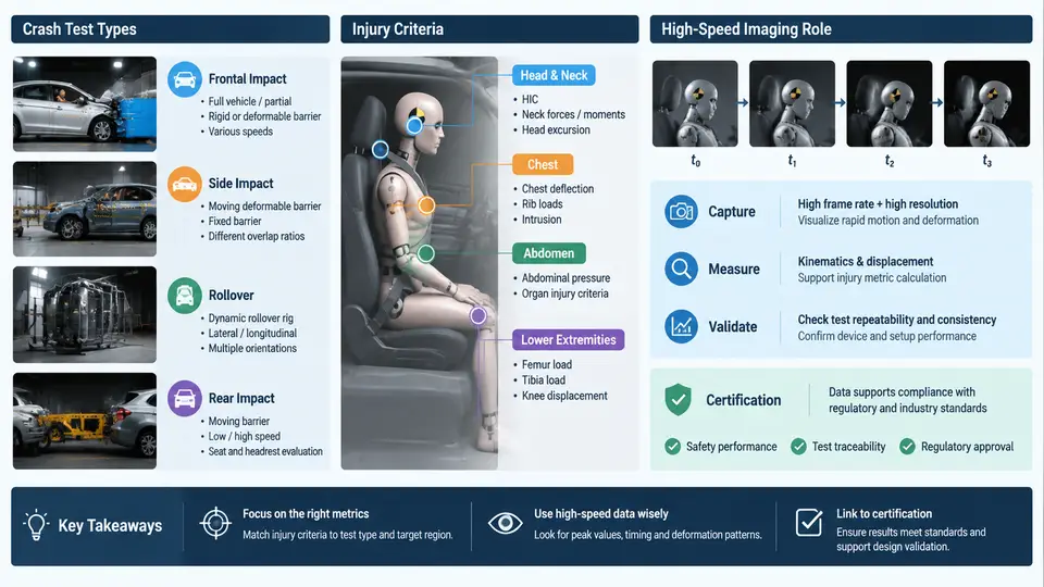
Occupant safety testing is the discipline of reproducing, in a controlled and repeatable way, the deceleration events that a human body may experience in a road collision, and then measuring how the restraint system and vehicle structure manage the energy transferred to that body. The purpose is not simply to destroy vehicles; it is to generate quantitative evidence that a design meets a defined protection target. Three elements must always be present: a representative crash pulse, an anthropomorphic test device (ATD) or human body model, and a measurement chain that converts physical motion into injury-relevant numbers. High-speed imaging is the fourth, often underestimated element, because it is the only instrument that records the entire event spatially and temporally rather than at a few discrete points.
Crash Test Types and What Each One Validates
Crash configurations are defined by the impact direction, the overlap between the striking and struck objects, and the velocity change (Delta-v). The most common categories are frontal full-width rigid barrier, frontal offset deformable barrier (ODB), side impact with a moving deformable barrier (MDB), side pole, rear impact, and pedestrian or cyclist impact. Each configuration loads a different part of the occupant's body and therefore stresses a different part of the restraint system.
| Test type | Typical impact speed | Primary validation target | Dominant ATD response |
|---|---|---|---|
| Frontal full-width rigid barrier | 50 km/h | Belt and airbag load path, seat structure | Head, chest, femur |
| Frontal offset deformable barrier (40% overlap) | 64 km/h | Structural intrusion, occupant compartment integrity | Head, chest, lower leg |
| Side MDB (mobile deformable barrier) | 50 km/h | Side structure, side airbag, door trim | Thorax, abdomen, pelvis |
| Side pole | 32 km/h | Head-to-pole contact, curtain airbag coverage | Head, thorax |
| Rear impact (moving barrier) | Variable | Seat back strength, head restraint geometry | Neck (whiplash) |
The numbers above are representative regulatory and consumer-program values, not universal constants; the exact speed, barrier mass, and barrier stiffness are specified by the applicable regulation or rating protocol. A frontal full-width test at 50 km/h produces a short, high-magnitude pulse, whereas the 64 km/h ODB test produces a longer pulse with significant structural deformation. The engineer must know which pulse the restraint system is being tuned for, because airbag firing time and belt load limiter force are both pulse-dependent.
Injury Criteria: Turning Motion into a Pass/Fail Number
Raw accelerometer and load-cell signals are not directly comparable to a protection requirement. Injury criteria are biomechanical transfer functions that convert measured physical quantities into a normalized risk index. The most frequently used criteria in occupant safety are:
- HIC (Head Injury Criterion) — integrates resultant head center-of-gravity acceleration over the most severe 15 ms window. A common limit is HIC₁₅ ≤ 700 for a 50th-percentile male ATD in a frontal test.
- 3 ms clip — the maximum chest resultant acceleration that is not exceeded for more than 3 ms. A typical limit is 60 g.
- Chest deflection — the physical compression of the rib cage, often limited to 50–60 mm depending on ATD type.
- Nij (Neck Injury Criterion) — combines axial force and bending moment to predict neck injury.
- Femur force — axial compression limit, commonly 10 kN per leg.
- Viscous Criterion (VC) — the product of chest compression velocity and compression, used for soft-tissue injury risk.
These criteria are evaluated from filtered channels. The standard filter for HIC is CFC 1000 (Channel Frequency Class), while chest deflection and femur force are typically filtered at CFC 600 and CFC 600 respectively. Applying the wrong filter class changes the peak value and can move a result from pass to fail. The measurement chain therefore matters as much as the crash itself.
Worked example — HIC calculation from a recorded acceleration trace. Suppose the head resultant acceleration (in g) is sampled at 10 kHz and the most severe 15 ms window contains the following simplified values: 40, 55, 70, 82, 90, 88, 80, 68, 55, 42 g at 1.5 ms intervals. The HIC formula is:
HIC = [ (1/(t2 - t1)) * ∫ a(t) dt ]^2.5 * (t2 - t1)
    = [ (1/0.015) * (sum of a_i * dt) ]^2.5 * 0.015
With the values above, the integral approximates 1.02 g·s, so the mean acceleration is 68 g. HIC = 68^2.5 × 0.015 ≈ 3,810. This is far above the 700 limit, which tells the engineer that the head contact occurred too early or the airbag did not absorb enough energy. The next step is to inspect the high-speed footage to see whether the head hit the airbag before it was fully inflated or whether it bottomed out against the steering wheel.
The Role of High-Speed Imaging in Validation and Certification
Accelerometers and load cells give numbers but no spatial context. High-speed cameras fill that gap by recording the event at 1,000 to 10,000 frames per second, which is fast enough to resolve airbag deployment, belt spooling, and head trajectory. In a certification context, the camera record is not decorative; it is used to verify that the test was valid, that the ATD did not contact a non-representative surface, and that the restraint system deployed as intended.
Three imaging tasks are standard in a frontal crash test:
- Onboard camera — mounted on the vehicle floor or seat frame, looking at the occupant from the side. It shows the relative motion between the head, chest, and airbag.
- Offboard high-speed camera — positioned outside the vehicle, often at 1,000 fps, to record the overall vehicle motion and barrier interaction.
- Airbag deployment camera — a high-frame-rate camera (5,000–10,000 fps) focused on the module to verify inflation timing and seam opening.
The imaging data is synchronized with the sensor data using a common trigger, usually a contact switch on the barrier or a pre-trigger signal from the data acquisition system. Without synchronization, a frame showing the head at the airbag surface cannot be correlated with the acceleration peak, and the validation argument collapses.
The diagram above shows how the physical event, the sensor set, and the imaging system converge into a single validation output. The critical engineering point is that the image data and the sensor data must share a common time base. In practice, the trigger signal is recorded on both the DAQ and the camera controller, and the offset is measured with a calibration pulse before the test. A typical offset tolerance is less than one frame period; at 1,000 fps that is 1 ms, which is small compared with the 15 ms HIC window but large compared with airbag deployment timing.
Practical Validation Workflow and Failure Symptoms
A reproducible validation workflow for a frontal offset test can be summarized as follows. First, define the input: vehicle mass, impact speed, barrier type, ATD type and seating position, and the target injury criteria. Second, prepare the measurement chain: mount accelerometers at the ATD head CG, chest, and pelvis; install belt load cells; verify camera framing and focus; and confirm the trigger source. Third, execute the test and record all channels. Fourth, process the data with the correct CFC filters and compute the injury criteria. Fifth, review the high-speed footage frame by frame to confirm that the ATD kinematics match the assumptions used in the criteria calculation.
Common failure symptoms and their likely causes include:
- HIC exceeds the limit but the airbag looks fully inflated in the footage. Check the head-to-airbag contact time; the airbag may be too stiff or the venting may be insufficient. Also verify that the head accelerometer is not saturating.
- Chest deflection is high while vehicle deceleration is normal. Inspect the belt geometry and load limiter setting. A belt routed too high on the chest increases deflection without changing the vehicle pulse.
- Image and sensor data are misaligned. Recheck the trigger offset calibration. A one-frame shift at 1,000 fps can move the apparent head contact by several milliseconds.
- Airbag deployment appears late in the footage. Compare the deployment time with the crash pulse. If the airbag fires after the head has already moved forward, the sensing algorithm or the firing threshold needs adjustment.
When reviewing high-speed footage, always watch the first 100 ms at reduced playback speed before looking at the injury numbers. The eye catches mechanical interference, belt slip, and airbag seam issues that a single acceleration peak cannot explain. The numbers tell you how much; the images tell you why.
In certification, the high-speed record is part of the formal test documentation. Regulatory bodies and consumer rating programs require that the cameras cover the occupant compartment, that the frame rate is sufficient to resolve the event, and that the images are retained with the sensor data. The validation argument is therefore both quantitative and visual: the injury criteria demonstrate compliance with the limit, and the imaging demonstrates that the test represented the intended scenario. Together they form the evidence chain that connects a crash test to a real-world safety claim.