1. Full-vehicle crash testing overview
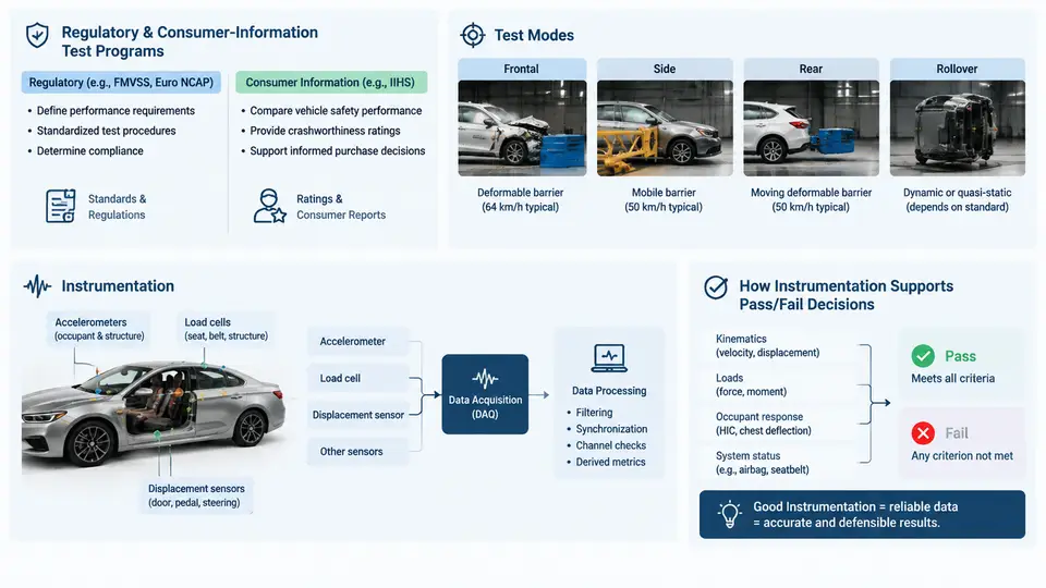
A full-vehicle crash test is a controlled, instrumented destruction of a complete vehicle against a defined barrier, moving object, or impactor at a prescribed speed and geometry. Its purpose is not simply to observe damage, but to produce defensible, repeatable measurements that determine whether occupants would be protected and whether a vehicle complies with a legal or consumer-information requirement. Every element of the test — the barrier, the impact angle, the speed tolerance, the dummy, the sensor set, and the pass/fail thresholds — is fixed by the program under which the test is conducted. Understanding which program governs a given test, and how instrumentation feeds the final decision, is the foundation for all subsequent work in this course.
Regulatory versus Consumer-Information Programs
Crash test programs fall into two broad families. Regulatory (homologation) programs are legally binding: a vehicle cannot be sold in a given market unless it passes. Examples include FMVSS 208 (occupant crash protection) and FMVSS 214 (side impact) in the United States, and UN Regulation No. 94 (frontal offset) and No. 95 (side impact) under the UNECE framework adopted in many other markets. These programs define mandatory test modes, injury criteria, and hard limits. A single exceedance can block certification.
Consumer-information programs are voluntary but highly influential. They publish comparative star ratings rather than legal verdicts. The two dominant examples are the U.S. New Car Assessment Program (US NCAP) and the European New Car Assessment Programme (Euro NCAP). These programs typically run at higher severity than regulation, add new test modes ahead of legislation, and combine multiple tests into a weighted score. A vehicle can be fully legal yet earn a poor consumer rating, which directly affects market position.
The practical consequence for the test engineer is that the same physical vehicle may be tested several times under different protocols, each with its own speed, barrier, and scoring. The test setup must be reconfigured precisely between programs; a barrier face or impact speed carried over from one program to another will invalidate the result.
Common Test Modes
Although programs differ in detail, most full-vehicle tests belong to a small set of modes:
- Full frontal rigid barrier — the vehicle strikes a flat, non-deforming wall at 100% overlap. Used to assess restraint system performance and structural integrity.
- Frontal offset deformable barrier (ODB) — typically 40% overlap against a honeycomb barrier, concentrating deformation on one side and stressing occupant compartment intrusion.
- Side impact (moving deformable barrier, MDB) — a trolley with a deformable face strikes the stationary vehicle perpendicular or at an oblique angle, targeting the near-side occupant.
- Side pole — the vehicle is propelled sideways into a rigid pole, producing a narrow, severe intrusion path.
- Rear impact — a moving barrier strikes the stationary vehicle from behind, primarily evaluating seat and head-restraint performance.
- Rollover — quasi-static roof crush or dynamic rollover, assessing roof strength and occupant retention.
Each mode imposes a distinct loading path on the structure and a distinct motion on the occupants, so the instrumentation plan must be matched to the mode rather than reused blindly.
The Role of Instrumentation in Pass/Fail Decisions
Instrumentation converts a violent, one-shot event into quantitative evidence. The chain begins with transducers: accelerometers on the vehicle structure and on the dummy, load cells in the barrier and in restraint components, displacement and intrusion sensors, and high-speed cameras for qualitative confirmation. Signals pass through signal conditioning (amplification, anti-alias filtering) and are digitized by a data acquisition system (DAS) at a defined sample rate, commonly 10 kHz or higher for crash pulses.
Raw data are then processed according to the governing standard. Accelerometer signals are filtered per SAE J211 (Channel Class 60, 180, or 600 depending on the measurement), and injury criteria are computed from the filtered channels. The most common criteria include:
| Criterion | Measurement basis | Typical role |
|---|---|---|
| HIC (Head Injury Criterion) | Resultant head acceleration, 36 ms window | Head injury limit |
| Nij (Neck Injury Criterion) | Neck axial force and bending moment | Neck injury limit |
| Chest deflection / VC | Chest displacement and velocity | Thoracic injury limit |
| Femur force | Axial load in femur load cell | Lower-extremity limit |
The pass/fail decision is made by comparing these computed values against the thresholds defined by the program. Critically, the decision depends on data quality as much as on the physical outcome. A channel that clips, drops out, or is filtered incorrectly can produce a value that is either falsely passing or falsely failing. This is why instrumentation integrity is treated as part of the test result, not as a separate technical concern.
How the Elements Connect
The diagram below shows how a program's requirements flow through the test setup into the instrumentation chain and finally into the pass/fail decision. It also shows the two feedback paths that matter in practice: setup must be verified against the protocol before the run, and data quality must be verified before the decision is accepted.
Practical Implications for the Test Engineer
Three habits separate a reliable crash test program from a fragile one. First, treat the protocol as the single source of truth: before every run, confirm barrier type, overlap, impact speed and its tolerance, dummy configuration, and channel list against the current version of the governing document. Programs are revised periodically, and a setup that passed last year may no longer be valid.
Second, verify the instrumentation chain before the destructive event. A pre-run channel check — shunt calibration, zero offset, and a tap test on accelerometers — catches most failures while the vehicle is still intact. Once the barrier is released, there is no second chance.
Third, treat data quality as a gate, not an afterthought. Before computing HIC or Nij, confirm that no channel clipped, that sample rates and filter classes match the standard, and that time-zero is consistent across channels. A decision built on a saturated accelerometer is not a decision; it is a guess.
With this framework in place — program, mode, setup, instrumentation, and decision — the remaining chapters can move into the specifics of each test mode, the selection and placement of sensors, the processing standards, and the documentation that makes a crash test result defensible.