1. Restraint system environmental qualifica
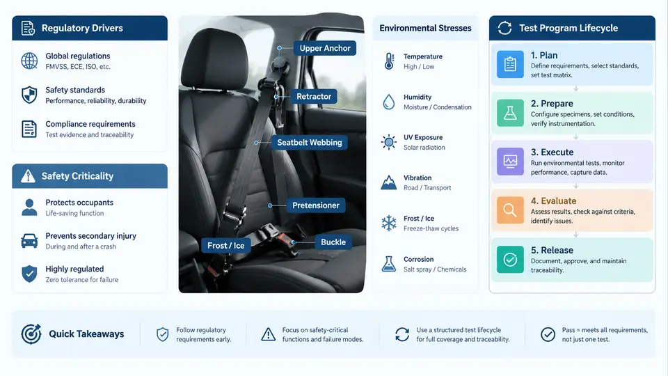
Restraint systems — seat belts, pretensioners, load limiters, airbag modules, and the occupant classification sensors that arm them — are among the few vehicle subsystems whose failure mode is measured in human lives rather than warranty cost. Environmental qualification (EQ) is the engineering discipline that demonstrates, with documented evidence, that these systems will deploy correctly and predictably across the full range of thermal, mechanical, electrical, and chemical environments they will encounter over a 15-year vehicle life. This chapter establishes why EQ exists, what makes restraint systems safety-critical in a regulatory sense, and how a qualification program is structured from requirements definition through final report.
Regulatory and Standards Drivers
EQ requirements for restraint systems do not originate from a single document. They arrive from three overlapping sources, and a competent program must satisfy all three simultaneously.
- Homologation regulations define the minimum legal performance. FMVSS 208 (occupant crash protection), FMVSS 209 (seat belt assemblies), and FMVSS 226 (ejection mitigation) in the United States; UNECE R16, R94, and R95 in Europe; and GB 11551 / GB 14166 in China. These specify the crash pulse, dummy type, and pass/fail injury criteria, but they generally test at nominal ambient conditions.
- Consensus and OEM standards fill the environmental gap. SAE J211 defines instrumentation practice; ISO 16750-4 (climatic loads) and ISO 16750-3 (mechanical loads) define test severities for electrical and electronic equipment on road vehicles; USCAR-2 and LV124 define connector and electrical performance; and each OEM publishes its own component specification (often called a "component test specification" or CTS) that is contractually binding.
- Functional safety and quality standards impose process discipline. ISO 26262 assigns Automotive Safety Integrity Levels (ASIL) to restraint functions — a frontal airbag deployment loop is typically ASIL D, the highest level — which mandates traceability from hazard analysis through validation evidence. IATF 16949 governs the production quality system that must sustain the qualified design.
The practical consequence is that a restraint ECU or buckle pretensioner may carry a dozen applicable documents. The qualification engineer's first task is to build a requirements traceability matrix that maps every environmental stress to its source clause, so that no test is performed "because we always do it" and no clause is silently omitted.
Why Restraint Systems Are Safety-Critical
Three properties distinguish restraint systems from ordinary automotive electronics and drive the rigor of EQ.
Latent failure with no operator feedback. A degraded airbag squib circuit or a corroded pretensioner connector produces no warning to the driver until the moment of a crash. Unlike a failing infotainment unit, there is no degraded-mode operation the customer can perceive. This means environmental damage must be prevented by design margin, not detected by the user.
Single-shot, irreversible actuation. A pyrotechnic initiator fires once. There is no second attempt, no retry logic, and no opportunity to compensate for a marginal condition at the moment of deployment. The qualification must therefore prove function at the worst-case combination of stresses, not the average.
Extreme environmental exposure combined with long dormancy. A seat belt retractor in a parked vehicle in Phoenix can see 85 °C interior soak temperatures; the same vehicle in Minnesota sees −40 °C cold starts. The system must remain armed and functional after 15 years of thermal cycling, vibration, humidity, and salt exposure — while never having been actuated.
The Test Program Lifecycle
A qualification program moves through five phases. Each phase has a defined entry condition, a defined output, and a gate review before the next phase begins.
Phase 1 — Requirements and DVP definition. The Design Verification Plan (DVP) is the master document. It lists every test, the sample size, the stress level, the duration, the acceptance criterion, and the source requirement. A typical DVP for a buckle assembly might contain 40–80 line items. Sample size is driven by statistical confidence: demonstrating 95% reliability at 90% confidence with zero failures requires a minimum of 29 samples per test cell, which is why DVP sample counts are often 30 or more.
Phase 2 — Test setup and fixture validation. Before any qualification sample is tested, the fixture itself must be validated. For vibration testing, this means a sine sweep to confirm the fixture's first natural frequency is at least 1.5× the highest test frequency, so the fixture does not amplify or attenuate the input. For thermal chambers, it means mapping air temperature at the unit under test (UUT) location, not just at the chamber sensor.
Phase 3 — Sequential stress application. Most restraint EQ programs use a sequential rather than independent stress model, because real vehicles experience combined and cumulative damage. A common sequence is: thermal shock → humidity soak → vibration → mechanical shock → functional check. The functional check at the end is the pass/fail gate.
Phase 4 — Functional verification and post-test inspection. After environmental exposure, the UUT undergoes deployment or actuation testing. For a pretensioner, this means firing the pyrotechnic charge and measuring stroke, force, and timing. For an ECU, it means verifying squib loop resistance, deployment timing, and diagnostic fault reporting.
Phase 5 — Reporting and traceability closure. Every test result is linked back to its DVP line item and its source requirement. Failures trigger a root-cause investigation and a design change, which restarts the affected portion of the lifecycle.
Worked Example: Buckle Pretensioner Qualification
Consider a seat belt buckle with an integrated pyrotechnic pretensioner, targeted for a global platform. The DVP calls for 30 samples through the sequential profile shown above, followed by actuation testing.
Inputs: 30 production-intent buckles, lot-controlled; thermal chamber capable of −40 °C to +125 °C; electrodynamic shaker with a fixture whose first mode is above 300 Hz; humidity chamber at 85 °C / 85% RH; shock machine capable of 50 g / 6 ms half-sine.
Execution: Samples undergo 100 thermal shock cycles (−40 °C to +85 °C, 15-minute dwell), then 500 hours at 85 °C / 85% RH, then 8 hours per axis of random vibration per ISO 16750-3 profile, then three mechanical shocks per axis at 50 g / 6 ms. After each stress block, squib loop resistance is measured; the acceptance window is 1.8–2.5 Ω at 23 °C.
Observable verification: After the full sequence, each unit is fired at −35 °C (cold worst case) and at +85 °C (hot worst case). Pass criteria: pretensioner stroke ≥ 85 mm, peak force within ±15% of nominal, actuation time ≤ 12 ms, and no mechanical fracture of the buckle housing. Squib resistance must remain within the 1.8–2.5 Ω window before firing.
Typical failure symptoms and troubleshooting: If squib resistance drifts above 2.5 Ω after humidity soak, the likely cause is connector terminal corrosion or moisture ingress at the squib interface. Corrective action: verify IP rating of the connector, add a hydrophobic seal, and re-run the humidity block on a reduced sample set before restarting the full sequence. If vibration causes a buckle housing crack, the fixture may be over-constraining the UUT; check fixture resonance and mounting torque before blaming the design.
Closing the Loop
The lifecycle is not linear in practice. A failure in Phase 4 sends the program back to Phase 1 for a requirements review, or to Phase 2 for a fixture investigation, or to the design team for a material change. What makes the program defensible is not that it never fails — it is that every failure is documented, root-caused, corrected, and re-verified with traceable evidence. That traceability chain, from regulatory clause to test result to design change, is the actual deliverable of environmental qualification.