1. Crash test data acquisition system engin
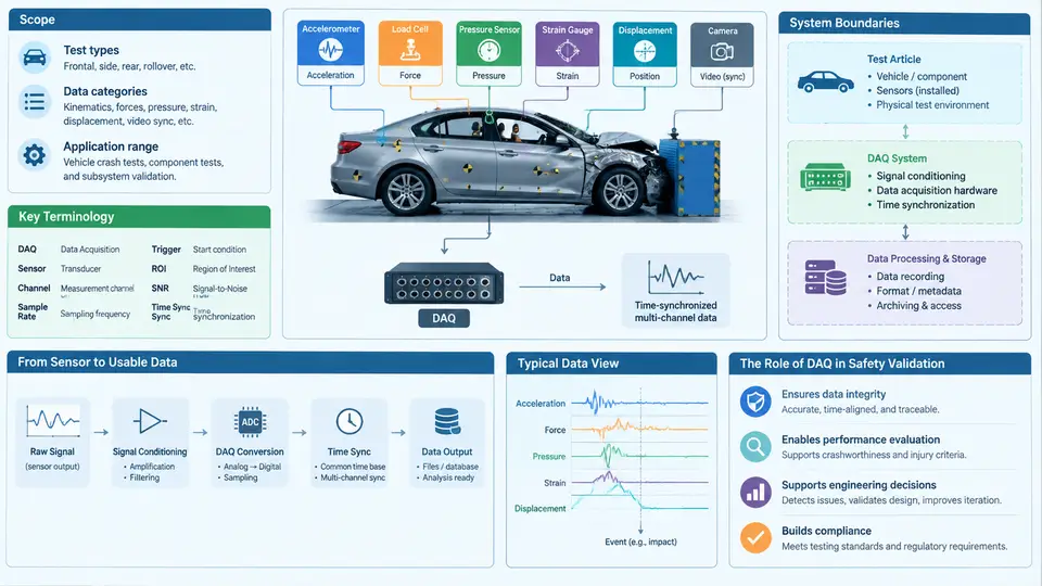
A crash test lasts roughly 100 to 150 milliseconds from bumper contact to rest. Inside that window, a vehicle structure folds, restraints deploy, and occupants load belts and airbags. Engineering decisions worth millions of dollars — whether a restraint fires 8 ms earlier, whether a rocker panel absorbs another 4 kJ, whether a door latch survives a pole impact — are made from measurements taken during those milliseconds. The discipline that turns physical events into defensible numbers is crash test data acquisition system (DAQ) engineering.
This chapter defines what that discipline covers, fixes the vocabulary used throughout the course, and draws the boundary between the DAQ system and everything it touches.
What the Discipline Covers
Crash test DAQ engineering is the end-to-end practice of capturing, conditioning, digitizing, validating, and delivering time-series measurements from a destructive vehicle test. It is not simply "hooking up sensors." A defensible measurement chain includes:
- Measurement planning — selecting channels, ranges, sample rates, and filter classes from the test objective (frontal rigid barrier, offset deformable barrier, side MDB, pole, rear, or sled).
- Transducer selection and mounting — accelerometers, load cells, string potentiometers, angular rate sensors, pressure sensors, and strain gauges, each with its own mounting stiffness and mass-loading constraints.
- Signal conditioning — bridge excitation, amplification, anti-alias filtering, and shunt calibration.
- Digitization and time base — synchronized sampling across on-board and off-board recorders, with a common trigger and a shared clock.
- Data validation and processing — zero-offset correction, SAE J211/1 filtering, integration to velocity and displacement, and channel-level plausibility checks.
- Documentation and traceability — channel tables, calibration records, and metadata that let a reviewer reproduce every number.
The output of this chain feeds occupant injury criteria (HIC, Nij, chest deflection, femur load), structural assessments, restraint timing studies, and regulatory or consumer-program submissions. If the DAQ chain is wrong, every downstream conclusion is wrong — and in a destructive test, there is no second chance to re-measure.
Key Terminology
The following terms are used with precise meanings throughout this course. Ambiguity here causes real errors, so treat them as controlled vocabulary.
| Term | Meaning in crash test DAQ |
|---|---|
| Channel | One conditioned, digitized measurement path: transducer → cable → conditioner → ADC → stored signal. |
| CFC (Channel Frequency Class) | Filter class defined by SAE J211/1 (CFC 60, 180, 600, 1000), specifying the low-pass corner and tolerance band for a channel type. |
| Full scale (FS) | The configured input range of a channel; resolution and clipping behavior follow from it. |
| Shunt calibration | Injection of a known resistor across a bridge leg to verify the full analog path gain before the test. |
| T0 | Time zero, the reference instant for all channels, typically defined by the barrier contact switch or a defined acceleration threshold. |
| On-board vs. off-board | Recorders mounted in the vehicle (survive the crash, short cables) vs. in the control room (more channels, long cables, higher noise risk). |
| Pre-trigger | Data retained from before T0 so the trigger instant and baseline are visible. |
| Pulse duration | Time from first contact to separation or rest; sets the required record length. |
Two conventions deserve emphasis because they cause the most cross-team confusion. First, sign convention: in this course, vehicle longitudinal acceleration is positive in the direction of travel, so a frontal impact produces a negative acceleration pulse unless a channel is explicitly inverted. Second, filtering is part of the measurement definition, not post-processing cosmetics — a HIC computed from CFC 1000 data is not the same number as one computed from CFC 60 data, and both may be legitimate for different purposes.
System Boundaries
A DAQ system has a clear inside and outside. Getting the boundary wrong is the most common source of "the data looked fine but the result was wrong."
Inside the boundary: transducers and their mounting interfaces, cabling and connectors, signal conditioners, the recorder and its ADC, the trigger and time-base distribution, on-board power, and the data files plus their metadata.
Outside the boundary but coupled to it: the test article itself (its structural response is the measurand, but its deformation can sever cables), the barrier or impactor, the propulsion system, the photographic and video systems, and the occupant positioning equipment. These interact with the DAQ through mechanical shock, electromagnetic noise, and shared trigger signals.
Where DAQ Sits in Vehicle Safety Validation
Vehicle safety validation is a chain: requirements → CAE simulation → component and sled tests → full-scale crash tests → regulatory and consumer submission. DAQ is the only link that produces physical evidence. Simulation predicts; DAQ adjudicates. This gives DAQ engineering three non-negotiable properties:
- Traceability — every channel must be traceable to a calibrated transducer, a documented mounting location, and a known filter class.
- Survivability — the system must keep recording through 40 g to 100 g shocks, cable severing, and loss of vehicle power.
- Time coherence — all channels, on-board and off-board, must share a time base accurate to well under 1 ms, because restraint timing decisions are made at that scale.
The figure below shows the measurement chain and the boundary between the DAQ system and the coupled test environment.
An Illustrative Channel Plan
To make the scope concrete, consider a 56 km/h frontal rigid barrier test of a mid-size sedan. The DAQ engineer must translate the test objective into a channel table before the vehicle is instrumented. A representative excerpt (illustrative values, not measured results) might look like this:
Ch   Location              Transducer        Range     CFC   Rate
--------------------------------------------------------------
01   B-pillar, left        accelerometer     ±500 g    60    20 kHz
02   B-pillar, right       accelerometer     ±500 g    60    20 kHz
03   Tunnel, floor         accelerometer     ±200 g    60    20 kHz
04   Steering column       accelerometer     ±200 g    180   20 kHz
05   Driver belt load      load cell         0–15 kN   600   20 kHz
06   Driver chest          IR-TRACC          ±75 mm    600   20 kHz
07   Driver femur, left    load cell         0–10 kN   600   20 kHz
08   Brake pedal force     load cell         0–5 kN    600   20 kHz
09   Seat track, left      string pot        0–250 mm  60    20 kHz
10   Door latch, left      strain gauge      ±5000 µε 1000   20 kHz
Three engineering decisions are embedded in that table. The range must be large enough to avoid clipping at peak but small enough to preserve resolution — a ±500 g accelerometer on a channel that peaks at 60 g wastes most of its dynamic range. The CFC follows the physical quantity: structural accelerations use CFC 60, occupant loads use CFC 600, and strain uses CFC 1000. The sample rate must be at least ten times the CFC corner to keep the anti-alias filter transition band manageable; 20 kHz is a common working value for occupant channels.
Before the test, each channel is verified by shunt calibration: a known resistor is switched across the bridge, and the recorded step must match the predicted equivalent input within tolerance. A channel that fails shunt cal is not "probably fine" — it is removed from the test or repaired, because a destructive test cannot be repeated.
What Success Looks Like
A DAQ system has done its job when, after the crash, an independent reviewer can open the data set and answer four questions without asking the test team: What was measured, where, with what transducer and filter? When was T0, and how was it established? Is the baseline zero correct, and is the signal free of clipping, dropouts, and cable-induced artifacts? And can every channel be traced to a calibration record? If any answer is missing, the measurement is not evidence — it is only a recording.
The rest of this course builds the engineering practice behind each of those answers, from transducer physics and mounting mechanics through signal conditioning, synchronization, validation, and the documentation that makes crash test data defensible.