1. Sled testing program fundamentals
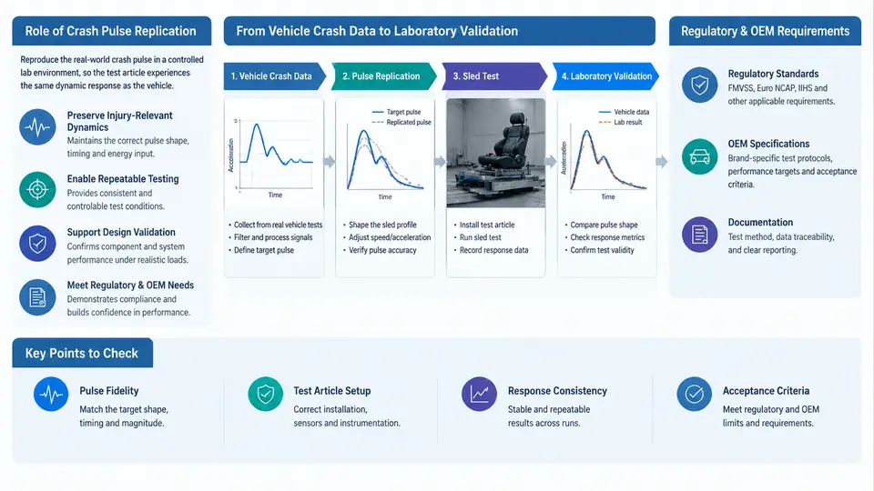
A sled test program exists to answer one question with confidence: if this seat, restraint, airbag, or battery pack were installed in a real vehicle, would it protect the occupant or survive the crash? Full-vehicle crash testing answers that question directly, but each destructive test consumes a complete vehicle, a dedicated facility slot, and weeks of instrumentation and teardown. A sled program decouples the structure under test from the vehicle body and reproduces only the motion that matters — the crash pulse — so that dozens of component variants can be evaluated against the same, repeatable input.
This chapter establishes the vocabulary and workflow that the rest of the course builds on: what a crash pulse is, why replication fidelity determines whether a sled result is meaningful, which regulatory and OEM requirements drive the pulse definition, and how a program moves from recorded vehicle crash data to a validated laboratory test.
What the Sled Reproduces — and What It Does Not
A crash sled is a guided carriage that accelerates or decelerates a mounted test buck according to a prescribed acceleration–time history. The buck carries the seat, restraint system, steering column, instrument panel, or battery module in the same geometric relationship it has in the vehicle. The sled does not reproduce crush, structural intrusion, or the deformation of the vehicle body. That is the central trade-off: the sled gives repeatability and cost efficiency in exchange for removing the very structure that, in a real crash, absorbs energy and sometimes intrudes into the occupant space.
Because intrusion is absent, the sled pulse must be chosen deliberately. Two philosophies dominate:
- Acceleration-based pulse — the buck is accelerated to a target velocity and then decelerated by a programmable brake or by a deceleration sled, matching the vehicle's occupant-compartment deceleration history.
- Velocity-based pulse — the sled is driven to a prescribed velocity change (Δv) with a controlled deceleration profile, often used when the requirement is stated as a barrier-equivalent Δv rather than a full acceleration trace.
In both cases the quantity being replicated is the occupant-compartment acceleration history, not the vehicle's center-of-gravity acceleration. Confusing the two is one of the most common early-program errors, because the two signals differ substantially once crush and engine/body motion are involved.
Regulatory and OEM Requirements
Pulse requirements arrive from two directions, and a mature program satisfies both.
Regulatory requirements define the minimum legal envelope. FMVSS 208 (frontal occupant protection), FMVSS 207/210 (seat and anchorage), FMVSS 213 (child restraint systems), ECE R16/R94/R137, and GB 11551/GB 15083 are typical drivers. These standards usually specify a corridor — a bounded acceleration–time envelope — rather than a single trace. A test pulse is compliant if it stays inside the corridor at every time step, and the corridor is defined over a stated velocity range and test configuration.
OEM requirements are typically stricter and more specific. A vehicle manufacturer will extract a pulse from its own barrier or pole test, or from a CAE-simulated crash, and issue it as a sled pulse specification with a tolerance band, a required Δv, and a required pulse duration. OEM specifications often add requirements the regulation does not: a specific pulse shape (e.g., a trapezoidal or half-sine approximation), a defined rise time, and a limit on the deviation between commanded and achieved pulse.
From Vehicle Crash Data to Laboratory Validation
The workflow below is the backbone of every sled program. Each stage has a defined input, a defined output, and a defined acceptance check.
- Acquire vehicle crash data. Source signals come from a full-vehicle barrier test (accelerometers on the occupant compartment, sampled at 10 kHz or higher) or from a validated CAE model. The raw signal is filtered per SAE J211 (typically CFC 60 for occupant-compartment acceleration) before it is used.
- Define the target pulse. The filtered acceleration history is converted into a target pulse: a Δv is computed by integrating acceleration, and the pulse is trimmed to the duration of interest. The result is a target acceleration–time trace plus a tolerance corridor.
- Design the sled input. The laboratory must produce that trace. For a deceleration sled this means selecting brake profile, sled mass, and initial velocity; for an acceleration sled it means programming the thrust profile. The design is iterative — a first-pass profile is simulated, then adjusted.
- Run the sled test. The buck, instrumentation, and dummy (or component) are installed, the pulse is commanded, and the achieved sled acceleration is recorded.
- Validate the achieved pulse. The achieved trace is filtered identically to the target, then compared against the corridor. Acceptance criteria typically include: every sample inside the corridor, Δv within tolerance (commonly ±1 to ±2 km/h), and pulse duration within tolerance.
- Release the test. Only after pulse validation is the occupant or component response considered valid. A test with a passing dummy response but a failed pulse is not a valid test.
The critical insight is that pulse validation is a gate, not a formality. If the achieved pulse drifts outside the corridor, the dummy response is measuring a different event than the one the requirement describes, and the result cannot be used to demonstrate compliance.
Worked Example: Building a Target Pulse
Suppose a full-vehicle frontal barrier test yields an occupant-compartment acceleration signal. After SAE J211 CFC 60 filtering, the signal is integrated to obtain Δv. Assume the integration returns a Δv of 48 km/h over a 110 ms window — this is an illustrative value, not a measured result. The program's OEM specification requires a sled pulse with Δv = 48 ± 2 km/h and a duration of 100–120 ms.
The engineer then fits a target shape. A common approach is a trapezoid: a rise to peak acceleration, a plateau, and a decay. If the plateau is set at 40 g and the pulse is trapezoidal with 15 ms rise and 15 ms decay, the Δv is approximately:
Δv ≈ a_peak × (t_rise/2 + t_plateau + t_decay/2)
   = 40 g × (0.0075 s + 0.080 s + 0.0075 s)
   = 40 × 9.81 × 0.095 m/s
   ≈ 37.3 m/s ≈ 134 km/h   ← inconsistent with the 48 km/h target
The arithmetic immediately shows the plateau is far too high for the required Δv and duration. Reducing the plateau to about 14 g over the same timing gives Δv ≈ 47 km/h, which is inside the ±2 km/h band. This is exactly the kind of first-pass check that saves a wasted sled run: the target pulse must be internally consistent with its own Δv and duration before any hardware is committed.
Program Roles and Data Flow
A sled program is a chain of custody for a signal. The crash data owner provides the source trace; the pulse engineer defines the target and corridor; the sled operator executes; the instrumentation engineer records; the validation engineer compares achieved versus target; and the occupant-safety engineer interprets the response. If any link substitutes its own assumption for the agreed pulse definition, the program loses traceability.
Acceptance Criteria in Practice
Pulse validation is judged against explicit numeric criteria. A representative acceptance set — values here are illustrative and must be replaced by the governing specification — looks like this:
| Parameter | Typical requirement | How it is checked |
|---|---|---|
| Corridor containment | Every sample inside upper/lower bounds | Sample-by-sample comparison after identical filtering |
| Velocity change (Δv) | Target ± 1–2 km/h | Integrate achieved acceleration over pulse window |
| Pulse duration | Within specified window (e.g., 100–120 ms) | Time between onset and end thresholds |
| Filter class | Same CFC applied to target and achieved | Confirm channel metadata and filter settings |
| Onset definition | Consistent threshold (e.g., 0.5 g) | Verify both traces use the same onset rule |
Two failure modes dominate early programs. First, filter mismatch: the target was filtered at CFC 60 but the achieved trace was left unfiltered or filtered at a different class, producing an apparent corridor violation that is purely an analysis artifact. Second, onset misalignment: the two traces are time-shifted, so the comparison is made between different portions of the event. Both are corrected in analysis, not by re-running the sled — but only if the engineer recognizes them.
With this foundation — the purpose of replication, the two requirement sources, the six-stage workflow, and the validation gate — the next step is to examine the pulse itself in detail: how acceleration–time histories are characterized, how corridors are constructed, and how a target pulse is translated into a commandable sled input.