1. Automotive safety laboratory automation
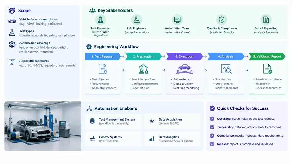
An automotive safety laboratory is not a single room full of sled tracks and crash barriers. It is a distributed measurement enterprise in which test articles, instrumentation, data acquisition systems, analysis software, and human reviewers must stay synchronized across weeks or months. Automation engineering in this environment means designing the connective tissue that carries a test from an initial request all the way to a signed, validated report — reliably, traceably, and without silent data loss.
This chapter maps that landscape: what falls inside the automation scope, who the stakeholders are, and how a test request becomes a validated report. Later chapters drill into individual subsystems; here we establish the end-to-end reference model that every subsequent design decision must respect.
Scope of Laboratory Automation
Automation in a safety lab spans four layers, and confusing them is the most common source of failed projects.
- Test execution layer — sled and crash propulsion control, dummy positioning rigs, door-closing actuators, airbag trigger units, and environmental conditioning. These are real-time, safety-critical systems with hard interlocks.
- Measurement layer — onboard data acquisition (DAQ) units, accelerometers, load cells, angular rate sensors, high-speed cameras, and the sensor calibration database that gives every channel a physical meaning.
- Data and workflow layer — the laboratory information management system (LIMS) or test management system, file naming and storage conventions, filtering and processing pipelines, and the traceability records that link a raw file to a report line.
- Analysis and reporting layer — injury-criteria computation, occupant kinematics review, video synchronization, and generation of the customer-facing report.
A practical automation boundary is drawn where human judgment is legally or technically required. Filtering, unit conversion, channel validation, and report assembly are automatable. Deciding whether a dummy's neck response is acceptable, or whether a test is invalid due to an out-of-tolerance impact condition, remains a documented human decision — but the automation must present that decision with complete evidence.
Stakeholders and Their Requirements
Each stakeholder imposes a different constraint on the same data pipeline. Ignoring any one of them produces a system that works in the lab but fails in an audit.
| Stakeholder | Primary interest | Automation implication |
|---|---|---|
| Test requester / OEM customer | Test executed to a defined specification; results delivered on schedule | Request intake must capture the regulation or internal standard, configuration matrix, and acceptance criteria as structured data |
| Test engineer | Fast setup, reliable triggering, immediate visibility of channel health | Pre-test channel verification, automated zeroing checks, and live status dashboards |
| Technician / rig operator | Safe, repeatable mechanical setup | Position recipes, interlock status feedback, and setup checklists tied to the test ID |
| Data analyst | Consistent, correctly filtered, well-documented datasets | Deterministic processing pipelines with versioned filter definitions |
| Quality / accreditation body | Traceability from report value back to raw sensor signal | Immutable audit trail, calibration records, software version capture |
| Lab management | Facility utilization, cost per test, turnaround time | Scheduling integration and automatic milestone timestamps |
The tension between these groups is real. The test engineer wants to start the run; quality wants the calibration status confirmed first. A well-designed workflow resolves this by making the quality gate automatic and fast rather than a manual paperwork step.
The Engineering Workflow: From Request to Validated Report
The following reference workflow is the backbone of the rest of this course. It is described as a sequence of stages with defined inputs, outputs, and exit criteria — not as a rigid waterfall. In practice, stages overlap and iterate, but each stage has a gate that must be satisfied before the next one can be trusted.
Stage 1 — Test request intake
A request arrives as a specification: regulation clause (for example, a frontal offset impact requirement), vehicle or sled buck configuration, dummy type and seating position, impact velocity with tolerance, and the set of channels to be recorded. Automation converts this into a structured test order with a unique test ID. The critical engineering decision here is defining the channel list and sampling parameters at intake, because they determine the DAQ configuration, the storage estimate, and the analysis pipeline that will later run.
A typical intake record for a frontal sled test might specify: impact velocity 50 km/h ± 1 km/h, 32 channels at 10 kHz per channel for the occupant region, 4 high-speed cameras at 1000 fps, and a required report turnaround of 10 working days. These numbers propagate directly into resource planning.
Stage 2 — Preparation and configuration
The test ID drives everything downstream. The DAQ configuration file is generated from the channel list, sensor serial numbers are bound to channel numbers, and calibration factors are pulled from the calibration database with their validity dates. If a sensor's calibration expires before the scheduled test date, the workflow should flag it at this point — not on the morning of the test.
Stage 3 — Pre-test verification
Before the run, the automation performs a channel integrity check: shunt calibration or bridge excitation verification, zero-offset measurement, and a signal continuity test. Channels that fail are reported with the specific measured value and the tolerance band, so the technician can act. This is the last cheap opportunity to catch a problem.
Stage 4 — Test execution and acquisition
The propulsion system, trigger, and DAQ are armed in a defined order with hardware interlocks. The automation records the actual impact velocity, trigger time, and any abort condition. Immediately after the run, a quick-look dataset is produced so the engineer can confirm the test is broadly valid before the article is removed.
Stage 5 — Data processing
Raw data is filtered according to the applicable channel class (for example, a CFC 60 filter for certain occupant accelerations, CFC 180 or CFC 600 for others), zeroed to a defined pre-impact window, and converted to engineering units. Every processing step is logged with the filter class, cutoff frequency, and software version.
Stage 6 — Analysis and validation
Injury criteria are computed from the processed channels, and the results are compared against the acceptance criteria captured at intake. The validation gate checks three things: the test condition was within tolerance, the data quality is acceptable, and the computed values are complete. Only then does the report become eligible for release.
Stage 7 — Report generation and release
The report is assembled from templates populated by the analysis results, with figures and tables generated automatically. A reviewer signs off, and the release event is timestamped and recorded. The audit trail now links the report value back through the processing log to the raw channel and the sensor calibration record.
Where Automation Actually Pays Off
Not every step deserves the same investment. The highest-return automation targets are the ones that are repetitive, error-prone, and expensive to redo. Channel configuration and calibration binding are prime candidates: a single mislabeled channel can invalidate an entire test day. Processing pipelines are another: manual filtering with inconsistent cutoff frequencies makes results non-comparable across tests, which is fatal when a customer compares two configurations.
Conversely, over-automating the physical setup of a dummy or the mechanical preparation of a sled buck often produces fragile systems that technicians bypass. The practical rule is to automate the information flow aggressively and the physical manipulation conservatively.
Common Failure Modes at the Landscape Level
Three systemic problems recur across labs and are worth naming early, because the rest of this course addresses them repeatedly.
- Orphaned data. Raw files exist but cannot be linked to a test order, so they cannot be reported. This happens when file naming is manual and the test ID is not enforced at acquisition time.
- Version drift. The analysis software is updated, but old reports cannot be reproduced because the processing version was not recorded. Reproducibility requires capturing the pipeline version with every result.
- Gate bypass. Under schedule pressure, the pre-test verification or the validation gate is skipped, and the failure surfaces only at report review — after the test article is destroyed.
Each of these is an engineering workflow problem, not a hardware problem, and each is solvable with structured data, enforced gates, and complete logging. That is the subject of the chapters that follow.