1. Impact sensing system architecture
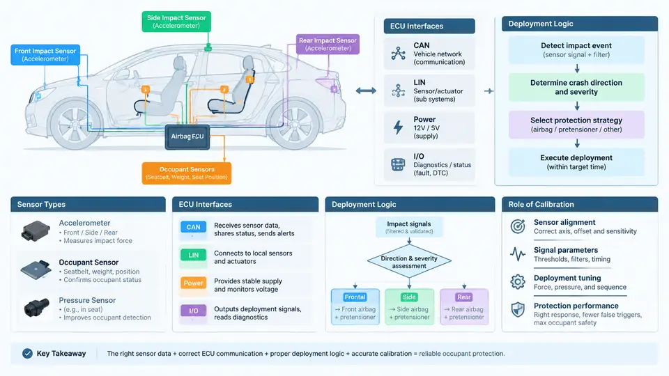
An automotive impact sensing system is a distributed, time-critical measurement chain whose only job is to decide, within a few milliseconds, whether a crash is severe enough to fire a restraint. The architecture is deliberately layered: remote sensors at the crush zone, a central airbag control unit (ACU, often called the SDM or RCM), and a firing stage that arms and deploys squibs. Calibration is what converts raw acceleration and pressure signals into a defensible deployment decision, and it is the single largest lever on whether an occupant is protected or unnecessarily injured by a late or spurious airbag.
Sensor Types and Their Physical Roles
Three sensor families dominate modern frontal and side impact sensing.
- Accelerometers (MEMS capacitive or piezoresistive). Frontal satellite sensors are mounted on the radiator support, crash box, or B-pillar base and measure longitudinal or lateral acceleration, typically ±50 g to ±500 g full scale. The ACU itself contains a central accelerometer, usually ±50 g, used as the primary crash reference.
- Pressure sensors. Side-impact pressure satellites sit inside the front door cavity and measure the rapid pressure rise when the outer panel deforms inward. They respond faster than a door-mounted accelerometer for pole and barrier side hits, with a typical measurement range around 300–600 kPa absolute.
- Contact and safing sensors. Mechanical or electronic safing switches, plus the ACU's internal safing accelerometer, provide an independent second channel that must agree before any squib is armed.
Each sensor is a two-wire or three-wire current-loop or PSI5 device. PSI5 (Peripheral Sensor Interface 5) is common for satellites because it carries data and power on the same two wires and supports synchronous or asynchronous modes with a 125 kbit/s or 189 kbit/s data rate.
ECU Interfaces and Signal Integrity
The ACU is the arbitration point. It polls satellites over dedicated sensor buses, performs plausibility checks, and drives the firing ASIC. A representative interface map is shown below.
| Interface | Typical Device | Signal / Rate | Purpose |
|---|---|---|---|
| PSI5 sensor bus | Front satellite accelerometer | 10-bit, 1 kHz sync | Crush-zone acceleration |
| PSI5 sensor bus | Door pressure satellite | 10-bit, 1 kHz sync | Side pressure rise |
| SPI / internal | Central accelerometer | 16-bit, 2 kHz | Primary crash reference |
| Firing ASIC | Squib drivers | Current-limited pulse | Deployment energy |
| CAN FD | Vehicle bus | 2 Mbit/s | Event data, diagnostics |
Signal integrity matters because a 1 ms delay at 50 km/h translates to roughly 14 mm of additional occupant travel. Sensor wiring is therefore shielded, twisted, and routed away from high-current harnesses. The ACU validates each satellite by checking its current signature, message CRC, and time-slot adherence; a missing or out-of-window frame is treated as a fault and logged as a DTC.
Deployment Logic and the Safing Concept
Deployment logic is a two-stage decision. The primary channel computes a crash severity metric from filtered acceleration or pressure. The safing channel independently confirms that a crash is occurring. Only when both agree does the firing ASIC close the squib circuit. This prevents a single sensor fault or EMI event from deploying a bag.
A simplified severity calculation for a frontal event uses a moving-window velocity change:
// Example: 5 ms sliding window, 2 kHz central accelerometer
// a[n] in g, converted to m/s^2
dv = 0;
for (k = n-9; k <= n; k++) {
    dv += a[k] * 9.81 * 0.0005;   // 0.5 ms sample period
}
if (dv > DV_THRESHOLD && safing_active) {
    fire_primary_stage();
}
Here DV_THRESHOLD is not a single number. It is a calibrated surface indexed by impact speed, ambient temperature, and seat-track position, because the same physical crash produces different occupant kinematics depending on where the seat sits.
Where Calibration Enters the Architecture
Calibration is the mapping from physical input to deployment decision. It includes sensor offset and sensitivity trim, filter coefficients, threshold tables, and timing delays. A typical frontal calibration set contains:
- Zero-g offset and sensitivity correction per satellite, stored in ACU NVM.
- Low-pass filter corner frequency, often 300–600 Hz for frontal, higher for side.
- Velocity-change threshold versus time (the "must-fire" and "must-not-fire" corridors).
- Safing threshold and arming delay.
- Stage-1 and stage-2 timing, typically 0–20 ms apart.
The calibration must satisfy two opposing requirements: fire early enough to protect, and never fire in a non-crash event such as a hammer blow, door slam, or rough road. This is validated against a matrix of crash pulses and abuse events.
Architecture Overview
Calibration's Role in Occupant Protection
The calibration determines the deployment envelope. A well-calibrated system fires the belt pretensioner early (around 10–15 ms) to remove slack, then the airbag at 15–25 ms so the bag is fully inflated before the occupant's head reaches the steering wheel. If the calibration is too conservative, the occupant loads an under-inflated bag and the head strikes the rim. If it is too aggressive, the bag fires in low-speed events and can cause injuries from the deployment itself, particularly to out-of-position occupants.
Regulatory and consumer tests define the boundaries. FMVSS 208 specifies must-fire and must-not-fire conditions; Euro NCAP and C-NCAP add offset and pole tests. The calibration engineer runs a DOE across impact speed, angle, temperature, and seat position, then fits thresholds that satisfy all corridors simultaneously. The final calibration is flashed into ACU NVM and verified by a production end-of-line test that checks sensor offsets and a simulated crash pulse.
In summary, the impact sensing architecture is a chain of specialized sensors, a central arbitration ECU, and a calibrated decision layer. The sensor types define what physical quantity is measured, the ECU interfaces define how reliably it arrives, the deployment logic defines when firing is allowed, and the calibration defines exactly where the line between protection and false deployment sits. Every downstream test—sled, barrier, abuse, and end-of-line—exists to prove that this line holds across the full operating space.