1. Facility planning fundamentals
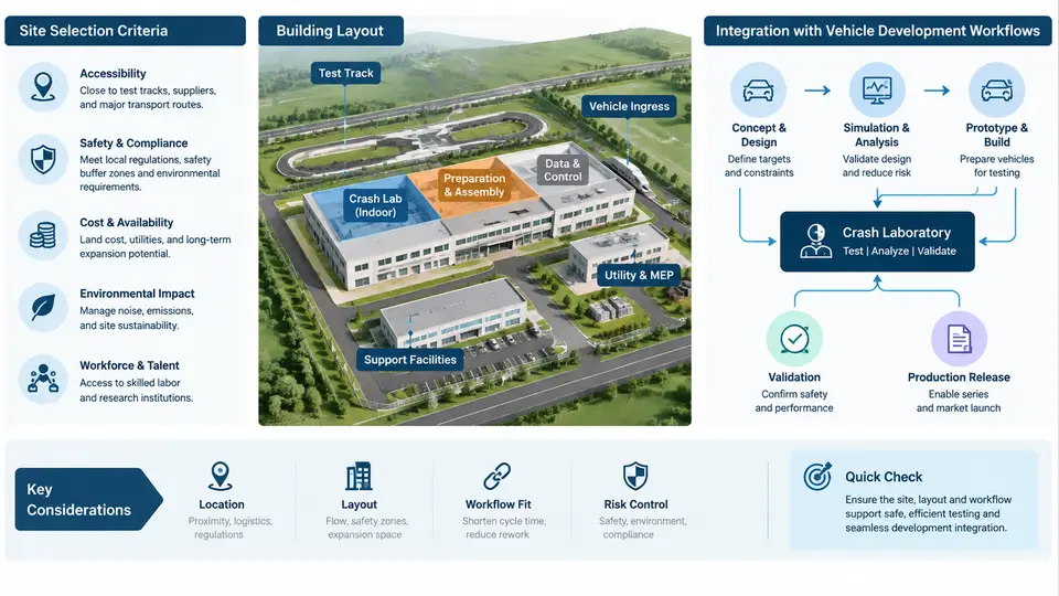
A crash laboratory is not simply a large hall with a concrete block at one end. It is a measurement instrument the size of a building, and like any instrument its accuracy, repeatability, and useful life are largely determined before the first sled is bolted down. Facility planning therefore sits at the front of the commissioning chain: decisions made about the site, the building envelope, and the relationship between the lab and the vehicle development process constrain everything that follows — test types, throughput, data quality, and future expansion.
Site Selection Criteria
Site selection for a crash facility is driven by a small number of hard constraints and a larger set of soft ones. The hard constraints are physical and legal; the soft ones affect operating cost and organizational fit.
Run-out distance and test envelope. The single most important geometric parameter is the distance available for the test article to travel, decelerate, and come to rest, plus the clearance needed for barriers, camera towers, and debris containment. A full-scale frontal barrier test at 64 km/h requires a run-up of roughly 60–100 m and a post-impact run-out of 15–30 m, depending on vehicle mass and barrier type. A side-impact or pole test needs less longitudinal distance but more lateral clearance. The site must accommodate the largest test in the planned portfolio with margin, not the average test.
Ground conditions and vibration isolation. The barrier foundation and the tow track must resist dynamic loads on the order of several hundred kilonewtons without settlement or rotation. Soil bearing capacity, water table depth, and bedrock profile all matter. Equally important is isolation from external vibration: a site adjacent to a rail line, a stamping press, or a high-traffic road will inject noise into accelerometer and load-cell signals. A useful rule of thumb is to keep the lab at least 100 m from continuous heavy vibration sources, or to plan a structurally isolated foundation slab.
Access, logistics, and utilities. Crash labs consume large amounts of electrical power (often 1–3 MW for tow systems and lighting), compressed air, and chilled water. They also generate noise, dust, and occasional fire risk. Sites should have adequate grid capacity, room for a substation, and a buffer zone to the nearest residential or office building. Vehicle delivery access — wide enough for a transporter and a forklift — is easy to overlook and expensive to retrofit.
Regulatory and organizational fit. Zoning, environmental permits for fuel and battery handling, and proximity to the vehicle development center all influence the choice. A lab 45 minutes from the design studio will be used less effectively than one on the same campus, because crash testing is iterative: a result often triggers a design change that must be re-tested within days.
Building Layout and Functional Zoning
Once the site is fixed, the building layout translates test requirements into physical zones. A well-planned crash lab separates four functions: preparation, test execution, measurement and control, and post-test processing. Mixing them creates congestion and compromises data quality.
The preparation bay is where vehicles are instrumented, ballasted, and checked. It needs a level floor, overhead crane coverage, and enough space to work around a full-size vehicle on all four sides. Adjacent to it should be a staging area where the vehicle waits before entering the test hall, so that the test hall itself is not occupied by non-test activity.
The test hall contains the tow track, the barrier or moving deformable barrier (MDB), the camera and lighting rigs, and the data acquisition front-end. Its dimensions are set by the largest test envelope plus clearance for camera towers and safe operator positions. The floor must be flat and level to within a few millimeters over the tow distance, because track alignment directly affects vehicle trajectory and repeatability.
The control room should be physically separated from the test hall by a wall with a viewing window and cable penetrations. This protects operators and electronics from debris and noise, and it keeps the data acquisition system in a stable thermal environment. The control room houses the tow controller, the DAQ, the camera control, and the communication system.
Post-test processing includes vehicle inspection, photography, and sometimes a tear-down area. It should be downstream of the test hall so that a tested vehicle can be moved out without crossing the path of the next test.
Integration with Vehicle Development Workflows
The layout above is only useful if it supports the actual development loop. In a typical vehicle program, crash testing is not a single event but a repeating cycle: CAE predicts performance, a prototype is built, a crash test validates or challenges the prediction, data is reviewed, and the design is revised. The facility must be planned around this cycle, not around a one-off test.
Three integration requirements follow from this. First, proximity to engineering matters because the cycle time between test and design decision is often measured in days. A lab on the same campus can support a test-and-review meeting within 24 hours; a remote lab adds travel and shipping time that can double the loop. Second, data compatibility matters: the lab's DAQ, coordinate conventions, and channel naming should match the CAE and test-data management systems used by the engineering team, so that results can be compared without manual translation. Third, capacity and scheduling must match the program's test matrix — a facility that can run only one test per day will bottleneck a program that needs twenty configurations validated in a month.
A useful planning exercise is to build a simple throughput model. Suppose a program requires 40 full-scale tests over 12 weeks, with each test occupying the hall for 6 hours including setup and teardown. That is 240 hall-hours, or about 20 hours per week — feasible in a single-shift operation with margin. If the requirement rises to 80 tests, the same hall needs either a second shift or a second test position. This kind of arithmetic, done early, prevents the common failure mode of a well-built lab that cannot keep up with the program it was built for.
Key Planning Parameters at a Glance
| Parameter | Typical Planning Value | Why It Matters |
|---|---|---|
| Run-up distance | 60–100 m for 64 km/h frontal | Determines maximum impact speed and test type |
| Post-impact run-out | 15–30 m | Safe deceleration and debris containment |
| Floor flatness | Within a few mm over tow distance | Trajectory repeatability and track alignment |
| Distance to vibration sources | ≥ 100 m or isolated slab | Signal quality for accelerometers and load cells |
| Electrical capacity | 1–3 MW | Tow system, lighting, HVAC, DAQ |
| Distance to engineering | Same campus preferred | Shortens the test–review–revise loop |
These values are planning-level estimates, not universal specifications. They should be refined against the specific test portfolio, local code requirements, and the vehicle platforms the lab is expected to support. The essential point is that site selection and building layout are not preliminary formalities to be rushed before the "real" commissioning work begins. They define the physical and organizational boundaries within which every later decision — barrier design, tow system selection, DAQ architecture, and safety systems — must operate.