1. Steering column collapse fundamentals
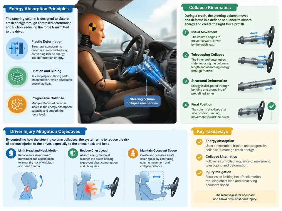
The steering column is the primary load path between the driver and the vehicle's steering system, and in a frontal crash it becomes the primary path for occupant injury. A rigid column that transmits steering inputs faithfully in normal driving will, in a collision, transmit crash energy directly into the driver's chest and head. Steering column collapse is the engineered solution: a controlled, predictable axial shortening of the column that absorbs energy and limits how far the steering wheel intrudes into the occupant compartment. This chapter establishes the physical principles behind that behavior, the kinematics of how a column collapses, and the injury-mitigation objectives that govern its design.
Why the Column Must Collapse
In a frontal impact, the vehicle's front structure decelerates the body, but the driver continues forward at the pre-impact velocity until restrained by the seat belt and airbag. The steering column sits directly in that relative motion path. Two distinct hazards arise. First, occupant intrusion: if the column does not shorten, the steering wheel and column move rearward relative to the occupant compartment as the front structure crushes, reducing the survival space. Second, energy transfer: a stiff column acts as a rigid beam that concentrates force on the driver's chest through the wheel and airbag interface.
Collapse addresses both. By allowing the column to shorten axially at a controlled force level, the column absorbs a portion of the relative kinetic energy and simultaneously limits rearward displacement of the wheel. The design target is not "as soft as possible" — a column that collapses too easily cannot transmit steering torque and will feel loose — but a tuned force–displacement characteristic that balances steering feel against crash energy management.
Energy Absorption Principles
The fundamental relationship is simple: the energy absorbed by a collapsing element equals the integral of force over displacement.
E_absorbed = ∫ F(x) dx (from x = 0 to x = collapse stroke)For a column designed to collapse at a roughly constant force F_c over a stroke s, the absorbed energy is approximately E ≈ F_c × s. This gives designers two levers: the collapse force level and the available stroke. Stroke is bounded by packaging — the distance between the column and the driver, and the space available behind the column. Force level is bounded by steering feel requirements and by the column's structural role.
Real collapse elements rarely produce a perfectly flat force–displacement curve. Common energy-absorbing mechanisms include:
- Rolled or inverted tubes that invert and fold as they shorten, producing a stable, high-efficiency crush force.
- Sliding collars with interference fits, where friction and plastic deformation of the mating surfaces set the collapse force.
- Shear pins or breakaway fasteners that release at a calibrated load, allowing a telescoping section to slide.
- Mesh or spline sliding joints that dissipate energy through friction and deformation during axial travel.
Each mechanism has a characteristic force trace. A shear-pin release produces a sharp initial peak followed by a lower sliding force; a rolled tube produces a relatively flat plateau. The designer selects and tunes the mechanism so the force trace stays within an acceptable corridor — high enough to absorb meaningful energy, low enough to keep chest loading within injury thresholds.
Collapse Kinematics
Kinematics describes how the column moves, not just how much energy it absorbs. Three kinematic behaviors matter most.
Axial collapse. The column shortens along its own axis, moving the wheel rearward less than the body moves forward. The collapse stroke is the axial travel available before the column bottoms out. Once bottomed out, the column becomes rigid again, so the stroke must be sufficient to cover the expected intrusion for the crash severity the design targets.
Column angle and wheel trajectory. The column is inclined, typically 20–30° from horizontal. As it collapses, the wheel does not move purely rearward; it follows the column axis, which means it also moves downward or upward depending on the inclination. This trajectory determines whether the wheel loads the driver's chest, abdomen, or face. Designers evaluate the wheel trajectory against the occupant's anthropometry to ensure the wheel does not concentrate load on a vulnerable region.
Bending and column breakaway. In some designs, the column is intended to bend or break away at a calibrated hinge or bracket, allowing the wheel to move away from the driver rather than into the driver. This is a kinematic strategy distinct from axial collapse: the column rotates about a pivot, redirecting the wheel path. The two strategies are often combined — axial collapse for energy absorption, breakaway for trajectory control.
Injury Mitigation Objectives
Collapse design is ultimately judged against occupant injury criteria. The objectives can be grouped into three tiers.
Primary objective — limit chest loading. The steering column and airbag together determine the force applied to the driver's chest. The column's contribution is governed by its collapse force and the wheel's contact pressure. Design targets are typically expressed against chest deflection and chest acceleration criteria (for example, a chest deflection limit on the order of 50 mm for a 50th-percentile male in a standardized frontal test). The collapse force corridor is set so that the column does not add excessive load on top of the airbag's contribution.
Secondary objective — control wheel intrusion and trajectory. The wheel must not intrude into the occupant's survival space beyond a defined limit, and its trajectory must not direct load into the neck or abdomen. This is where kinematics and packaging interact: the available stroke, column angle, and breakaway behavior are chosen together to keep the wheel in an acceptable zone throughout the crash pulse.
Tertiary objective — preserve steering function. The column must still transmit steering torque in normal operation and must not collapse under driver-applied loads (for example, a driver bracing on the wheel during hard braking). The collapse threshold must sit comfortably above the maximum expected steering and bracing loads, with margin for wear and temperature.
Putting the Principles Together: A Worked Example
Consider a column with a target collapse force of 2.5 kN and an available stroke of 120 mm. The nominal absorbed energy is approximately 2.5 kN × 0.12 m = 300 J. If the crash pulse delivers a relative occupant-to-vehicle displacement of 150 mm at the column, the column absorbs energy over the first 120 mm and then bottoms out, becoming rigid for the remaining 30 mm. That bottom-out phase is where chest loading spikes, which is why stroke margin matters: increasing stroke from 120 mm to 150 mm would eliminate the rigid phase entirely for this pulse.
Suppose testing shows the actual force trace peaks at 3.4 kN during the initial release and settles to 2.2 kN on the plateau. The peak exceeds the upper corridor limit and would raise chest loading. The fix is not to lower the plateau — that would reduce energy absorption — but to soften the release: reduce shear-pin diameter, add a chamfer to the sliding collar, or introduce a pre-crush feature that spreads the initial release over several millimeters. After the change, the peak should fall within the corridor while the plateau remains near 2.5 kN.
Verification follows a clear logic: measure the force–displacement trace on a servo-hydraulic sled or quasi-static press, integrate it to confirm absorbed energy, compare the peak and plateau against the corridor at cold, nominal, and hot temperatures, and confirm the bottom-out displacement exceeds the expected intrusion for the target crash severity. If any check fails, the mechanism geometry or material is adjusted and the trace re-measured.
Key Takeaways
- Collapse converts a rigid load path into a controlled energy absorber, limiting both wheel intrusion and chest loading.
- Absorbed energy is the area under the force–displacement curve; design levers are collapse force level and stroke.
- Kinematics — axial stroke, column angle, and breakaway behavior — determine where the wheel goes, not just how far.
- Injury objectives are tiered: chest loading first, wheel intrusion and trajectory second, steering function third.
- Verify the force trace against a corridor across temperature extremes and confirm stroke margin against expected intrusion.