1. Diagnose Initial Penetration in a Shell-
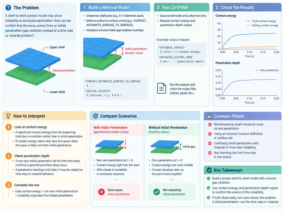
Why initial penetration is a distinct failure mode
In LS-DYNA shell-to-shell contact, the penalty stiffness is activated only when a slave node lies inside the master segment's contact thickness. If the model is built with the slave surface already inside that thickness at time zero, the solver applies a large corrective force on the very first cycle. The resulting contact energy spike, negative sliding energy, and "initial penetration" warning in the message file are frequently misread as a time-step or material problem. This case isolates the mechanism: a deliberately violated initial gap, a controlled run, and a diagnosis based on glstat contact energy and sleout penetration depth.
Minimal model with a known gap violation
The model uses two flat, square shell patches (100 mm × 100 mm, 1 mm thick) with *MAT_ELASTIC (steel: ρ = 7.85e-9 t/mm³, E = 210 GPa, ν = 0.3) and *SECTION_SHELL with five integration points. The lower patch is fully constrained at its perimeter; the upper patch is given an initial velocity of 5 m/s toward the lower one. The physical standoff is 2.0 mm, but the slave nodes are deliberately placed 0.6 mm inside the master contact thickness, so the initial gap is negative. That is the only intentional defect — everything else is a clean, stable setup.
*KEYWORD
*TITLE
Case 01 - Initial Penetration Diagnosis
*CONTROL_TERMINATION
         0.5
*CONTROL_TIMESTEP
       0.0       0.9
*CONTROL_ENERGY
         2         2         2         2
*DATABASE_GLSTAT
      1.0E-4
*DATABASE_SLEOUT
      1.0E-4
*DATABASE_RCFORC
      1.0E-4
*DATABASE_BINARY_D3PLOT
      1.0E-3
*PART
Lower plate
         1         1         1
*PART
Upper plate
         2         1         1
*SECTION_SHELL
         1         2       1.0         5
*MAT_ELASTIC
         1    7.85E-9  210000.0       0.30
*NODE
       1       0.0       0.0       0.0
       2     100.0       0.0       0.0
       3     100.0     100.0       0.0
       4       0.0     100.0       0.0
      11       0.0       0.0       2.0
      12     100.0       0.0       2.0
      13     100.0     100.0       2.0
      14       0.0     100.0       2.0
*ELEMENT_SHELL
       1       1       1       2       3       4
       2       1      11      12      13      14
*SET_NODE_LIST
         1
         1         2         3         4
*BOUNDARY_SPC_SET
         1         0         1         1         1
*INITIAL_VELOCITY_NODE
        11       0.0       0.0      -5.0
        12       0.0       0.0      -5.0
        13       0.0       0.0      -5.0
        14       0.0       0.0      -5.0
*CONTACT_AUTOMATIC_SURFACE_TO_SURFACE
         1         2         0         0         0         0
       0.0       0.0       0.0       0.0       0.0       0.0
       1.0       1.0
*SET_PART_LIST
         1
         1
*SET_PART_LIST
         2
         2
*END
Note the deliberate geometry: the upper patch sits at z = 2.0 mm, but the master shell thickness (1 mm) plus the default contact thickness offset means the effective contact surface extends to z ≈ 2.5 mm. The slave nodes at z = 2.0 mm are therefore 0.5 mm inside the master's contact thickness at t = 0 — a clean, reproducible initial penetration of roughly 0.5 mm.
Running and reading the diagnostic outputs
Run the deck with ls-dyna i=case01.k (or the equivalent solver invocation). Two outputs carry the diagnosis:
- Message file — search for
initial penetration. A healthy model reports zero or a handful of nodes below tolerance; this model reports all four slave nodes with penetration values near 0.5 mm. - glstat — the
contact energycolumn jumps to a non-zero value on the first cycle and thesliding energygoes negative. In a clean impact, contact energy starts at zero and grows only after the surfaces actually meet. - sleout — the penetration depth per slave node is reported at t = 0 with a value matching the geometric violation, then decays as the penalty force pushes the nodes out.
Separating initial penetration from time-step and material issues
The decisive test is a controlled comparison. Re-run the same deck with the upper patch moved to z = 3.0 mm (a positive 0.5 mm gap). If the contact energy now starts at zero, the sliding energy stays non-negative, and the penetration warning disappears, the instability is confirmed to originate from the initial penetration — not from the time step (which is unchanged) or the material (which is unchanged). The table below summarizes the expected signature of each candidate cause.
| Observation | Initial penetration | Time-step instability | Material issue |
|---|---|---|---|
| Contact energy at t = 0 | Non-zero, large | Zero | Zero |
| Sliding energy sign | Negative early | Oscillating | Normal |
| Penetration warning | Present at t = 0 | Absent | Absent |
| Effect of halving dt | Unchanged | Reduced | Unchanged |
| Effect of moving gap positive | Resolved | Unchanged | Unchanged |
Verification checklist
Before accepting the diagnosis, confirm each of the following against the run outputs:
- The message file lists the four slave nodes with initial penetration values consistent with the 0.5 mm geometric violation.
glstatshows contact energy non-zero on the first printed cycle and sliding energy negative during the early transient.sleoutreports penetration depth at t = 0 matching the geometric offset, decaying as the penalty force acts.- The controlled re-run with a positive gap produces zero initial contact energy and no penetration warning, with the same time step and material.