1. System context and regulatory drivers
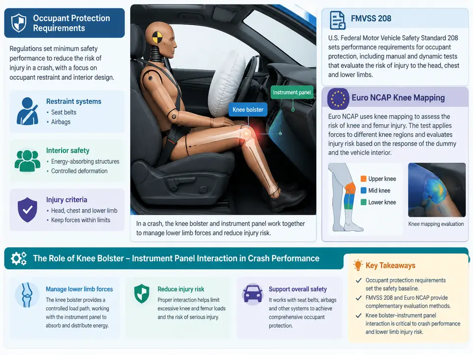
In a frontal crash, the occupant does not load the restraint system as a single point mass. The lap-and-shoulder belt, the airbag, the seat structure, and the lower instrument panel (IP) all share the deceleration of the body. The knee bolster is the trim and structural region of the IP that the occupant's knees and upper tibia contact when the pelvis moves forward and downward under belt loading. Its job is not merely cosmetic: it is the primary load path that controls femur compression, knee excursion, and pelvis kinematics before and during airbag engagement. Because the bolster is part of the IP, its stiffness, geometry, and attachment to the cross-car beam are inseparable from the IP structure itself. This chapter establishes the system boundary, the regulatory drivers, and why the knee bolster–IP interaction is a first-order crash-performance variable rather than a late-stage tuning detail.
Occupant protection requirements in frontal impact
Frontal occupant protection is governed by two complementary objectives. The first is injury mitigation: limit femur axial force, knee joint loading, and head/chest accelerations to biomechanically tolerable levels. The second is kinematic control: keep the occupant in a posture where the belt and airbag can do their work, and prevent submarining (the pelvis sliding under the lap belt) or excessive lower-extremity forward excursion. The knee bolster serves both. By presenting a compliant but firm surface to the knees, it reacts part of the occupant's forward momentum through the femur and pelvis, helping to seat the pelvis in the belt and reducing the tendency to submarine. At the same time, it must not be so stiff that it generates high femur loads or so soft that the knees punch through and the pelvis rotates out of position.
The interaction with the IP matters because the bolster is not a free-standing pad. It is mounted on the IP substrate, which is attached to the cockpit module and the cross-car beam. When the knee loads the bolster, the force travels through the bolster foam, the IP substrate, the mounting brackets, and into the body structure. If the IP substrate is too flexible, the bolster deflects as a membrane and the effective stiffness seen by the knee is low and nonlinear. If the substrate is too stiff or the bracket geometry creates a hard point, the knee sees a local spike. The design problem is therefore a system stiffness problem: the force–deflection characteristic at the knee contact patch is the series combination of bolster foam, IP substrate, brackets, and body structure.
FMVSS 208: the US regulatory baseline
FMVSS 208 (Occupant Crash Protection) is the primary US federal standard for frontal impact. For the driver and right-front passenger in belted frontal crashes, it specifies barrier tests (rigid barrier and, depending on configuration, offset deformable barrier) and defines injury criteria evaluated on instrumented Anthropomorphic Test Devices (ATDs). The criteria most relevant to the knee bolster are femur axial force and knee joint loading, evaluated from the ATD's upper leg and knee instrumentation. The standard also governs airbag deployment requirements and the unbelted test matrix, which is where lower-extremity loading often becomes critical because the belt is not sharing the load.
In practice, the FMVSS 208 test matrix forces the engineer to consider multiple configurations: belted and unbelted, driver and passenger, and different ATD sizes (e.g., 50th percentile male and, for out-of-position and small-stature evaluations, other sizes). The knee bolster must perform across this matrix. A bolster tuned only for the belted 50th percentile may produce excessive femur force in the unbelted case, where the knee engages earlier and with higher relative velocity. This is why the bolster–IP interaction is evaluated as a family of load cases, not a single test.
Euro NCAP knee mapping and the assessment philosophy
Euro NCAP takes a different but complementary approach. Its frontal offset test (currently the Mobile Progressive Deformable Barrier, MPDB, and the full-width rigid barrier test) evaluates occupant protection using ATD injury criteria, and the assessment includes knee mapping — a procedure that identifies where the occupant's knees contact the IP and how the IP responds at those locations. Knee mapping is used to understand the interaction between the lower extremities and the IP, to flag hard contact points, and to support the development of restraint systems that manage lower-extremity loading. The mapping is not a single pass/fail number; it is a spatial characterization of the IP surface and its stiffness at the knee contact zones, which is then correlated with ATD response and, increasingly, with human body model (HBM) simulation.
The Euro NCAP philosophy emphasizes real-world relevance: the offset test represents a partial overlap crash, and the knee mapping reflects the fact that the occupant's knees may contact the IP at various lateral positions depending on occupant size, seating position, and crash pulse. For the engineer, this means the bolster design must be robust across a contact patch, not just a nominal point. A bolster that is compliant at the center but stiff at the outboard edge, or vice versa, will show up as a non-uniform knee map and may indicate a hard point that needs attention.
Why the knee bolster–IP interaction is a first-order variable
The interaction matters for three reasons. First, load path continuity: the bolster is the first element in the lower-extremity load path, and its stiffness determines how much force reaches the femur and pelvis before the airbag and belt fully engage. Second, kinematic coupling: the bolster's force–deflection curve shapes pelvis rotation and submarining risk, which in turn affects chest and head loading through the belt. Third, spatial robustness: knee mapping and the multi-case test matrix require the bolster–IP system to behave predictably across contact locations and occupant sizes, which is a structural design problem, not a trim problem.
The figure below shows the system context: the occupant's lower extremity loads the bolster, the bolster transfers load into the IP substrate and brackets, and the IP is grounded to the cross-car beam and body structure. The regulatory drivers (FMVSS 208 criteria and Euro NCAP knee mapping) act on the resulting ATD response and IP surface characterization.
From regulation to design targets
The regulatory framework translates into concrete engineering targets. For FMVSS 208, the femur axial force and knee joint loading criteria define the allowable force ceiling at the knee contact patch, and the test matrix defines the load cases. For Euro NCAP, the knee mapping defines the spatial uniformity requirement and the offset/full-width tests define the crash pulses. The design response is a bolster–IP system whose force–deflection curve is tuned to stay below the force ceiling while providing enough reaction force to control pelvis kinematics, and whose stiffness is uniform enough across the contact patch to avoid hard points.
A practical way to frame the target is a force–deflection corridor. The lower bound is set by the need to react the knee and control submarining; the upper bound is set by the femur and knee injury criteria. The bolster foam, IP substrate, and brackets are then designed so that the measured or simulated force–deflection curve at the knee contact patch stays inside the corridor across the test matrix. This is the bridge from regulation to hardware, and it is the subject of the following chapters.
In summary, the system context is the occupant–bolster–IP–body load path, and the regulatory drivers are FMVSS 208's ATD-based femur and knee criteria plus Euro NCAP's offset/full-width tests and knee mapping. The knee bolster–IP interaction is a first-order variable because it sets the lower-extremity load path, couples to pelvis kinematics and submarining, and must remain robust across contact locations and occupant configurations. The next step is to characterize the bolster–IP system's force–deflection behavior and connect it to the regulatory corridors.