1. Frontal airbag system architecture
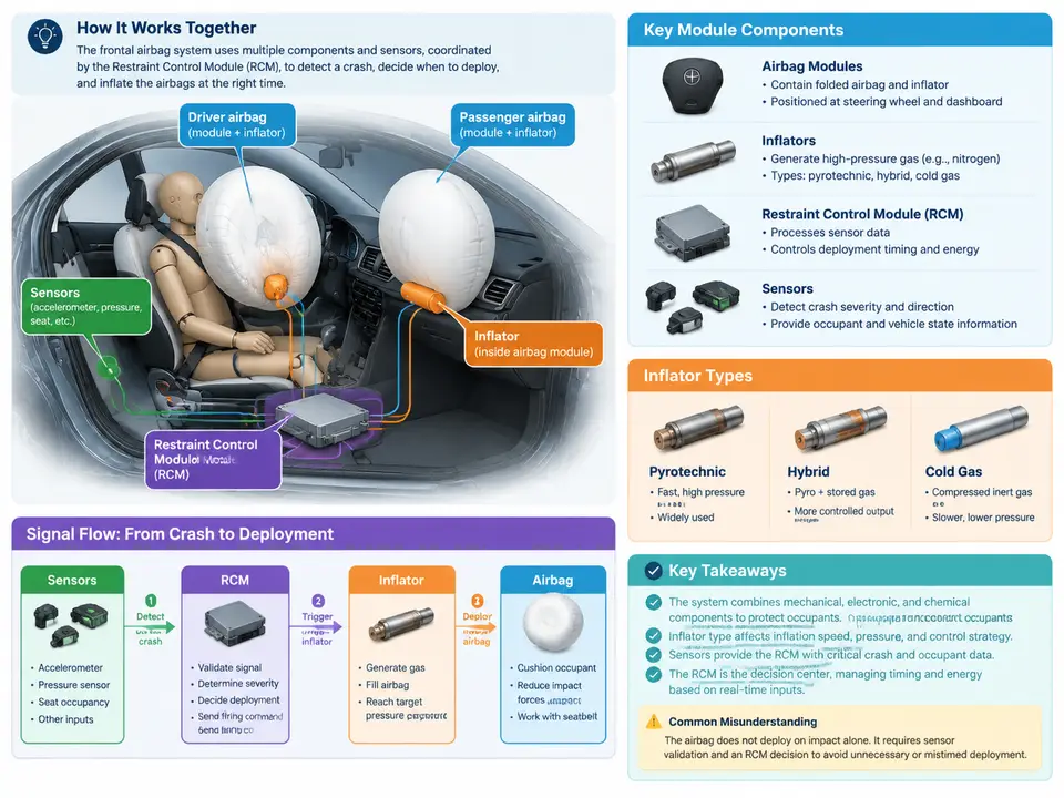
Before we can reason about when a frontal airbag should fire, we need a precise picture of the system that makes that decision and executes it. A frontal supplemental restraint system (SRS) is not a single device but a coordinated chain: crash sensors observe deceleration, the Restraint Control Module (RCM) classifies the event, and an inflator converts a stored chemical charge into gas that fills a folded cushion within tens of milliseconds. Understanding this architecture — the physical modules, the inflator families, the sensor suite, and the signal flow through the RCM — is the foundation for every timing and kinematics discussion that follows.
Physical Modules and Their Roles
A typical frontal system comprises four functional groups. The driver frontal airbag module is integrated into the steering wheel hub and contains the folded cushion, the inflator, and a retaining/housing structure. The passenger frontal airbag module sits behind the instrument panel on the passenger side and is substantially larger, because the cushion must span a wider distance to the occupant and the module must absorb the reaction forces of a bigger inflator. Both modules include a cover or tear seam designed to split predictably at deployment pressure rather than fragment.
The Restraint Control Module (RCM) is the electronic control unit — often mounted on the transmission tunnel or floor pan near the vehicle center of gravity, where it is least likely to be damaged in a crash and where its internal accelerometer best represents whole-vehicle deceleration. The RCM contains the microcontroller, the crash algorithm, the safing logic, the squib driver circuits, and the backup energy reserve (a capacitor bank that keeps the module alive for a short period if battery power is severed in the impact). Finally, the sensor suite and the wiring harness with clockspring complete the system: the clockspring carries the driver squib circuit and horn wiring across the rotating steering column.
Inflator Types
The inflator is the actuator that converts an electrical firing command into gas. Three families dominate frontal applications:
- Pyrotechnic inflators burn a solid propellant (historically sodium azide, now largely non-azide formulations) to generate gas directly. They are compact, fast, and inexpensive, and are common in driver modules.
- Hybrid inflators combine a small pyrotechnic charge with a stored compressed gas (typically argon or helium). The burning propellant heats and expands the stored gas, giving a cooler, longer gas delivery profile suited to larger passenger cushions.
- Stored-gas inflators release compressed gas via a pyrotechnic initiator without significant propellant combustion, producing the coolest fill and are used where thermal management matters.
Many modern systems add dual-stage or variable-output inflators: two independent squib circuits (primary and secondary) that the RCM can fire together, sequentially, or selectively depending on crash severity, occupant size, and belt status. This is the actuator-side mechanism that makes severity-adaptive deployment possible, and it is why the RCM's output is not a single "fire" line but a set of timed, individually controlled squib commands.
Sensor Suite
Frontal sensing typically uses three complementary sensor classes. Internal RCM accelerometers (often a primary and a redundant axis) measure vehicle longitudinal deceleration directly at the module. Front-end satellite sensors — accelerometers or pressure sensors mounted on the radiator support or bumper beam — detect the impact earlier than the RCM can, because the crash pulse reaches the front structure before it reaches the tunnel. Pressure-based satellite sensors detect the rapid pressure rise in a crushed bumper cavity and respond very quickly to soft, wide impacts. Safing sensors provide an independent, low-threshold confirmation path so that a single faulty primary sensor cannot command deployment; the safing function is often implemented as a separate electromechanical or electronic sensor in series with the firing loop.
Additional inputs refine the decision: seat track position sensors, occupant weight or classification sensors, buckle switches, and rollover sensors. These do not detect the crash itself but modulate the deployment decision — for example, suppressing or derating the passenger inflator when the seat is occupied by a small child or is empty.
RCM Signal Flow
The signal path from impact to inflation follows a consistent sequence. Satellite and internal accelerometers produce analog voltages proportional to deceleration; the RCM's signal conditioning filters and digitizes them at a fixed sample rate. The crash algorithm integrates and compares the resulting velocity change and energy measures against calibrated thresholds, evaluating them continuously over a short window (typically the first 20–50 ms). When the primary path and the safing path both agree that deployment is required, the RCM asserts the squib driver, which delivers a controlled current pulse to the inflator initiator. The inflator then generates gas, the cushion ruptures its cover and unfolds, and the whole sequence from first sensor contact to full cushion inflation is measured in tens of milliseconds.
Reading the Architecture in Practice
Consider a diagnostic scenario that exercises this signal flow. A technician connects a scan tool and reads a stored DTC indicating an open circuit on the passenger squib loop. The RCM has already performed its own continuity check by passing a small monitoring current through the squib circuit; an open circuit means the driver stage cannot deliver the firing pulse. The correct diagnostic path follows the architecture: verify the squib connector at the passenger module, check the harness for pinched or chafed conductors, and confirm the RCM's squib driver output with a breakout box rather than a multimeter alone, since the monitoring current is small and easily masked. This illustrates why the architecture matters — every fault is localized to a specific link in the sensor-to-inflator chain.
Key Takeaways
- The frontal SRS is a chain: sensors → RCM signal conditioning → crash algorithm and safing logic → squib drivers → inflators → cushions.
- Inflator type (pyrotechnic, hybrid, stored-gas) and staging determine the gas delivery profile and therefore the cushion's inflation timing.
- Satellite sensors buy early detection; the RCM accelerometers and safing sensor provide confirmation and fault tolerance.
- Occupant and position inputs modulate the decision but do not replace crash detection.
- Every diagnostic and timing question can be traced to a specific link in this architecture.