1. Euro NCAP knee mapping and sled test eva
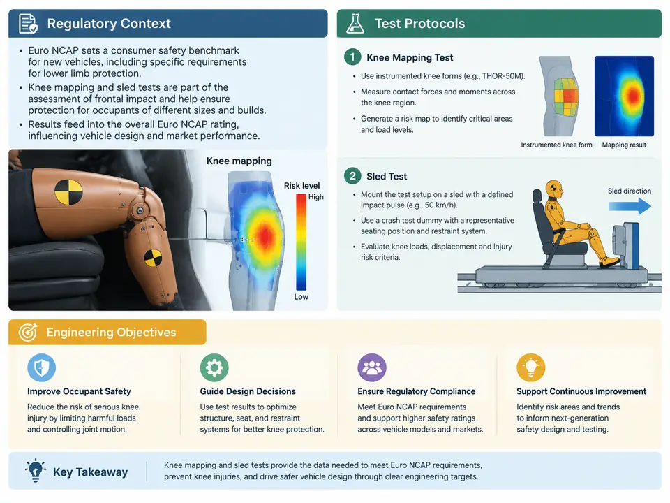
Knee mapping and sled test evaluation sit at the intersection of occupant packaging, restraint system design, and occupant protection assessment. In Euro NCAP's frontal impact assessment, the knee mapping procedure is used to establish the geometry and stiffness characteristics of the knee–thigh–hip region of the occupant, while the sled test provides a controlled, repeatable environment in which the performance of the restraint system and the vehicle interior can be evaluated against defined injury criteria. Understanding why these two activities exist, how they are specified, and what engineering questions they are meant to answer is essential before any measurement data can be interpreted meaningfully.
Regulatory and Assessment Context
Euro NCAP is a consumer-oriented assessment programme rather than a statutory type-approval regulation. Its protocols are published separately from UNECE regulations and are updated on a regular cycle, typically every few years, with interim amendments. This distinction matters in practice: a vehicle may satisfy UNECE R94 or R137 requirements and still fall short of Euro NCAP's more demanding assessment thresholds. The knee mapping and sled test procedures therefore belong to the assessment world, where the objective is to discriminate between vehicles and restraint systems rather than merely to demonstrate a minimum legal standard.
The frontal impact assessment in Euro NCAP combines full-width and offset deformable barrier tests with the sled-based evaluation of restraint performance. The sled test is not a vehicle crash; it reproduces the deceleration pulse measured in a reference barrier test and applies it to a body-in-white buck or a complete vehicle body mounted on the sled. This decoupling is the central engineering idea: by removing the variability of barrier deformation and vehicle-to-vehicle interaction, the sled test isolates the performance of the occupant restraint system and the interior surfaces that the occupant interacts with.
Knee mapping supports this isolation. The knee–thigh–hip region is a complex, non-uniform structure, and the interaction between the knee, the instrument panel, and the knee bolster depends strongly on where contact occurs and how the load is distributed. A mapping procedure characterises the geometry and force–deflection behaviour of the knee region so that the sled test setup, the positioning of the occupant, and the interpretation of contact loads are consistent and traceable.
What the Sled Test Protocol Specifies
A typical Euro NCAP sled test protocol defines the sled pulse, the occupant anthropometry, the seating position, the restraint configuration, and the measurement channels. The pulse is derived from a reference vehicle test and is applied through the sled's acceleration control system; the resulting occupant kinematics are then a function of the restraint system rather than the vehicle's structural crush. The occupant is normally a Hybrid III 50th percentile male, positioned according to the protocol's seating procedure, with the seat at the design position and the restraint routed as it would be in the vehicle.
Measurement channels include head acceleration, neck loads and moments, chest deflection, and femur loads, together with the knee contact forces where the protocol requires them. The evaluation is expressed through injury criteria such as HIC, Nij, chest deflection limits, and femur force limits, each with its own threshold and scoring band. The protocol also specifies the filtering and processing of the signals, because the same raw data can produce different criterion values depending on the channel frequency class applied.
Engineering Objectives
The engineering objectives of knee mapping and sled evaluation can be grouped into three areas. First, restraint system development: the sled test provides a repeatable platform for tuning airbag timing, force limiting, and seat belt load limiting before a full vehicle test is available. Second, interior packaging and knee bolster design: the knee mapping data inform how the lower extremity loads are distributed and whether the bolster stiffness is appropriate for the occupant's knee geometry. Third, robustness assessment: by varying occupant size, seating position, and pulse severity within the protocol's tolerance, the sled test reveals whether the restraint performance is sensitive to parameters that vary in real use.
These objectives shape how the results should be read. A sled test that meets all injury criteria at the nominal position but fails when the occupant is moved 20 mm forward is not a robust design, even though the nominal result looks acceptable. The knee mapping data are what allow the engineer to distinguish between a genuine restraint deficiency and a positioning artefact.
Reading the Protocol as an Engineering Document
Practitioners often treat the protocol as a compliance checklist. A more productive reading treats it as a specification of the experiment's boundary conditions. The pulse tolerance band tells you how much test-to-test variation is considered acceptable; the occupant positioning procedure tells you which degrees of freedom are controlled and which are left to the setup technician; the measurement channel list tells you which physical quantities the assessment actually cares about. When a result is unexpected, these three elements are usually where the explanation lies.
Consider a representative example. A sled test with a 50th percentile male occupant, a force-limiting retractor set to 4 kN, and a knee bolster with a nominal stiffness of 150 N/mm produces a peak femur load of 3.8 kN, close to but below the assessment threshold. The engineer wants to know whether the margin is real or an artefact of the setup. The knee mapping data show that the occupant's knee contacts the bolster 15 mm inboard of the design contact point, where the bolster is locally stiffer. Adjusting the bolster geometry to move the stiff region outboard, or softening the local section, changes the load path without altering the restraint system. A repeat sled test then confirms whether the femur load falls. This is the intended workflow: mapping informs the design change, and the sled test verifies it.
Key Parameters and Their Role
| Parameter | Typical Specification | Engineering Significance |
|---|---|---|
| Sled pulse | Derived from reference barrier test, with tolerance band | Defines the deceleration environment; deviations change occupant kinematics |
| Occupant | Hybrid III 50th percentile male | Sets the anthropometry against which criteria thresholds are defined |
| Seat position | Design position per protocol | Controls the distance to the bolster and the restraint geometry |
| Knee bolster stiffness | Characterised by mapping, e.g. 150 N/mm nominal | Determines the load distribution and the femur load magnitude |
| Signal filtering | Channel frequency class per protocol | Affects the computed criterion values from the same raw data |
Practical Takeaways
- Treat the sled test as an isolated restraint experiment, not a substitute for a full vehicle crash; its value lies in repeatability and parameter control.
- Use knee mapping data to explain contact location and local stiffness before attributing a femur load result to the restraint system.
- Verify pulse tolerance, occupant positioning, and signal filtering before comparing results across tests.
- Assess robustness by varying occupant size, seating position, and pulse severity within the protocol's tolerance, not only at the nominal condition.
The next stage of the course builds on this foundation by examining how the knee mapping procedure is executed in detail and how the resulting data are processed into a form usable for sled test setup and design decisions.