1. Crash test signal validation and sensor
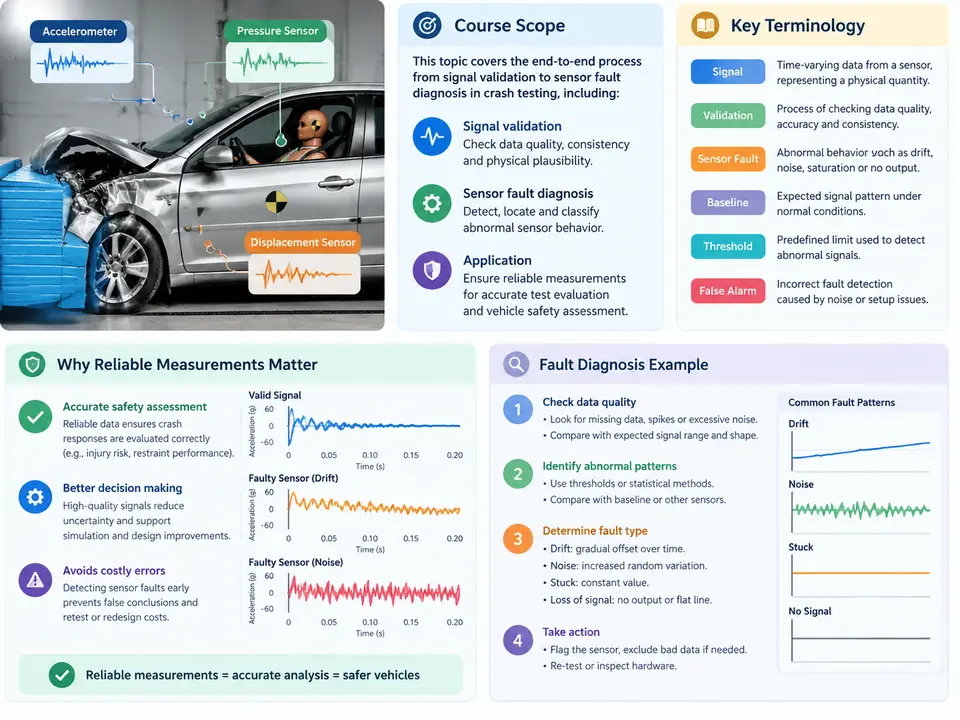
Crash testing is one of the few engineering disciplines in which a single measurement event, lasting roughly 100 to 150 milliseconds, determines whether a vehicle program proceeds, is redesigned, or is recalled. The data recorded during that event — accelerations, forces, displacements, and video — become the evidentiary basis for occupant protection assessment, restraint system calibration, regulatory certification, and, in some cases, litigation. This course addresses the discipline that sits underneath all of those downstream decisions: crash test signal validation and sensor fault diagnosis. The scope is deliberately narrow and technical: how to determine whether the signals you recorded are physically plausible, correctly scaled, properly time-aligned, and free of sensor-induced artifacts, and how to localize and characterize faults when they are not.
What This Course Covers — and What It Does Not
Signal validation in crash testing is not the same as data acquisition. Acquisition is the act of digitizing transducer outputs; validation is the engineering judgment applied to those outputs before anyone uses them to make a safety decision. The course therefore spans four connected domains:
- Measurement chain integrity — from transducer mounting and cabling through signal conditioning, anti-alias filtering, and digitization, including the failure modes each stage introduces.
- Physical plausibility checks — verifying that acceleration, force, and displacement records obey kinematic and dynamic constraints (integration consistency, zero-mean behavior before impact, bounded jerk, energy plausibility).
- Fault taxonomy and localization — distinguishing sensor faults (open circuit, saturation, drift, mounting resonance) from channel faults (gain error, offset, crosstalk) and from genuine physical events that merely look anomalous.
- Documentation and traceability — recording validation evidence so that a test report can withstand independent review.
The course does not teach occupant injury criteria in depth, nor does it cover sled or component-level test design except where those setups create specific signal-validation problems. The focus stays on the measurement itself.
Key Terminology You Will Use Throughout
Precision in vocabulary matters here because ambiguous terms cause real diagnostic errors. The following terms recur in every subsequent chapter.
| Term | Working definition in this course |
|---|---|
| Channel | A single digitized measurement path: transducer, cable, conditioning amplifier, filter, and ADC input, identified by a unique channel ID. |
| Zero offset (bias) | The channel output with the transducer at rest, measured during the pre-trigger window. Expressed in engineering units after calibration. |
| Pre-trigger window | The recorded interval before the trigger event (commonly 50–100 ms). Used for offset, noise floor, and drift assessment. |
| Time-zero (T0) | The reference instant from which all channel timing is measured, typically defined by a contact switch or optical barrier. Channel-to-channel T0 skew is a validation target. |
| CFC filter | Channel Frequency Class per ISO 6487 / SAE J211. Specifies the low-pass filter characteristic (e.g., CFC 60, CFC 180, CFC 1000) applied before analysis. |
| Saturation / clipping | Channel output reaching the full-scale limit of the conditioning range or ADC, producing a flat-topped waveform that destroys peak information. |
| Mounting resonance | A structural resonance of the transducer-to-fixture interface that appears as a high-frequency oscillation superimposed on the true signal. |
| Plausibility envelope | A pre-defined expected range and shape for a signal, derived from prior tests, simulation, or physical bounds, against which the record is compared. |
Two conventions deserve explicit statement because they govern every figure and calculation in this course. First, acceleration sign convention: unless a chapter states otherwise, positive acceleration is defined along the vehicle's forward axis, and occupant-cage accelerations during frontal impact are therefore predominantly negative (deceleration). Second, time reference: all timing is expressed relative to T0, with negative values in the pre-trigger window. Any deviation from these conventions is flagged at the point of use.
Why Reliable Measurements Are the Load-Bearing Wall
Consider what a single corrupted channel can do. A 5% gain error on a chest accelerometer channel shifts the calculated chest deflection and the resulting injury criterion by a comparable margin — enough to move a rating boundary. A 2 ms timing skew between the vehicle accelerometer and the seat-belt load cell makes the restraint firing sequence appear late, potentially triggering an unnecessary calibration change. A clipped peak on a femur load cell hides the true maximum and understates injury risk. In each case the physical test was executed correctly; the failure is purely in the measurement layer, and it propagates silently into every downstream conclusion.
The inverse error is equally costly: a genuine sensor fault misread as a physical anomaly can send engineers chasing a nonexistent structural problem through repeated, expensive full-vehicle tests. The discipline of validation exists to separate these two cases before either mistake is made.
The Validation Workflow at a Glance
The figure below shows how the measurement chain, the validation gates, and the fault-diagnosis branch relate. Note that validation is not a single pass/fail gate at the end; it is a sequence of checks applied at increasing levels of physical interpretation, with an explicit branch to fault localization whenever a check fails.
A Worked Example: Reading the Pre-Trigger Window
The most informative single check in the entire workflow is also the cheapest: inspecting the pre-trigger window. Suppose a uniaxial accelerometer channel is configured for ±500 g full scale with a CFC 1000 filter and sampled at 20 kHz, with a 100 ms pre-trigger window. In that window the vehicle is stationary, so the expected output is a flat trace at the channel's zero offset with only electronic noise present.
Three observations follow directly. First, the mean of the pre-trigger samples gives the offset; if the channel reads 0.8 g rather than 0.0 g, that bias will integrate into a spurious velocity error of roughly 0.8 g × 9.81 m/s² × 0.1 s ≈ 0.78 m/s if left uncorrected — a physically significant error in a 50 km/h (13.9 m/s) impact. Second, the peak-to-peak noise in the window establishes the noise floor; a channel showing 3 g peak-to-peak noise where comparable channels show 0.3 g indicates a loose connector, a damaged cable shield, or a failing bridge excitation. Third, any drift or step in the window indicates thermal effects or an intermittent connection that will corrupt the impact record itself.
What "Reliable" Means Operationally
Reliability in this context is not a vague quality; it decomposes into measurable properties. A channel is reliable when its accuracy (gain and offset within calibration tolerance), resolution (noise floor well below the smallest physically meaningful feature), bandwidth (anti-alias and CFC filtering appropriate to the phenomenon), timing (T0 skew within a stated bound, typically a small fraction of a millisecond), and integrity (no saturation, no dropouts, no mounting resonance contaminating the band of interest) have all been demonstrated and recorded. Each of these properties maps to a specific validation gate in the figure above, and each will be treated in detail in later chapters with concrete acceptance criteria and diagnostic procedures.
The remainder of this course builds outward from this foundation: the physics of each transducer type and its characteristic failure modes, the numerical checks that expose those failures, the diagnostic decision logic that localizes them, and the documentation practices that make the whole process auditable. The organizing question throughout is the same one posed at the start of this chapter — can this measurement be trusted to carry a safety decision, and if not, exactly where and why does it fail?