1. Course overview
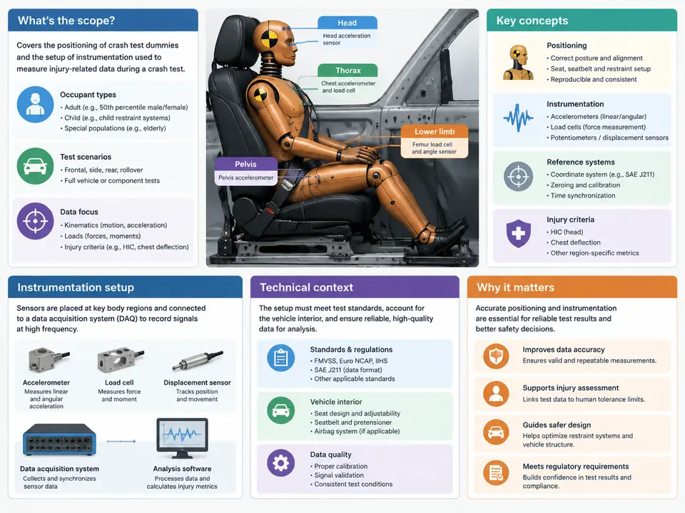
Crash test dummy positioning and instrumentation setup is the discipline that connects a physical anthropomorphic test device (ATD) to the validity of every number a crash test produces. A barrier impact, sled run, or component test can be executed flawlessly at the mechanical level and still yield unusable data if the dummy sits 15 mm too far forward, if its head is tilted 3° off vertical, or if a load cell is zeroed with a preload in the wrong direction. This course treats positioning and instrumentation as one integrated engineering problem: the dummy must be placed so that the occupant package, restraint system, and sensor suite all measure what the test program intends to measure.
The scope spans three interlocking domains. First, physical placement: seating the ATD in the vehicle or on the sled buck so that its posture, joint angles, and contact conditions match the regulatory or internal procedure being followed. Second, instrumentation: selecting, mounting, cabling, and verifying the transducers that convert dummy motion and loading into electrical signals. Third, documentation and traceability: recording the as-tested configuration so that results can be defended, repeated, and compared across builds. A test engineer who can do all three reliably is worth more than one who can only run the software.
Why positioning dominates result validity
Occupant restraint performance is highly sensitive to initial conditions. In a frontal 56 km/h barrier test, the driver airbag deploys within roughly 20–30 ms of impact; the dummy's chest-to-airbag distance at t = 0 determines whether the bag is fully inflated at contact or still expanding. A 20 mm change in seat track position can shift chest deflection by several millimetres and change HIC by double-digit percentages. Similarly, in side impact, the gap between the dummy's shoulder and the door trim controls how early the load path develops. Positioning is therefore not a cosmetic step before the "real" test — it is a controlled input variable, and it must be treated with the same rigor as impact speed or barrier mass.
The same logic applies to instrumentation. A triaxial accelerometer mounted on the head CG measures what the head actually experiences only if its sensitive axes are aligned with the head coordinate system and its mounting is rigid enough that resonance effects stay well above the measurement bandwidth. An ill-seated chest potentiometer, or a deflection sensor with a loose cable loop, can produce a plausible-looking trace that is physically wrong. The course therefore emphasizes verification before the event: static checks, sign conventions, channel zeroing, and pre-test range validation.
Coordinate systems and sign conventions
All positioning and instrumentation work in this course uses the SAE J211 / ISO 6487 convention unless a procedure states otherwise. For a seated dummy, the origin is at a defined reference point on the dummy (typically the H-point or a manufacturer-specified reference), with +X forward, +Y to the dummy's left, and +Z upward. Rotations follow the right-hand rule about these axes. Every sensor channel is labelled with its axis and polarity, and every positioning measurement is reported in this frame. When a test uses a different convention — for example, a vehicle-body frame with +X rearward — the transformation must be stated explicitly in the test record. Mixing frames silently is one of the most common sources of sign errors in post-test analysis.
The positioning–instrumentation workflow at a glance
The diagram below shows how the major work packages relate. Positioning decisions (seat, posture, joint angles) and instrumentation decisions (sensor selection, mounting, channel assignment) are made in parallel, then converge in a verification stage before the test event. Post-test, the as-tested record feeds back into both the positioning procedure and the instrumentation plan for the next build.
What "good" looks like: a worked positioning example
Consider a 50th-percentile male ATD (Hybrid III) being installed in the driver seat of a body-in-white buck for a 40 km/h frontal sled test. The procedure specifies a seat back angle of 25° from vertical, seat track at the mid-position, and the dummy's H-point within ±10 mm of the vehicle H-point in X and Z. The engineer first sets the seat using a digital inclinometer referenced to the buck floor, then places the dummy and uses a H-point machine or the dummy's own reference fixture to measure. Suppose the measured H-point is 14 mm rearward of target. The corrective action is not to "push the dummy forward" — it is to adjust the seat track one notch forward, re-measure, and confirm the seat back angle has not changed as a result. Only when both the seat and the dummy reference point are within tolerance does the engineer proceed to joint angle setting: hip 95° ± 5°, knee 120° ± 5°, and head tilt within 2° of vertical in the frontal plane.
Each of these numbers is a controlled input. The engineer records the as-measured values, not the target values, in the test log. If a joint cannot be brought within tolerance because of a hardware interference — for example, a knee bolster contact that prevents the specified knee angle — that deviation is documented and its potential effect on the result is noted. This is the difference between a test that can be defended and one that cannot.
Instrumentation context: what the sensors must capture
A typical frontal ATD carries 30–60 channels. The head has a triaxial accelerometer at the CG plus angular rate sensors; the neck has a six-axis load cell; the chest has a triaxial accelerometer and a deflection potentiometer; the pelvis and femurs carry load cells; the lower legs carry tibia load cells and knee-slider potentiometers. Each channel has a specified range (for example, ±2000 g for head acceleration, ±10 kN for femur load) and a specified filter class per SAE J211 (CFC 1000 for acceleration, CFC 600 for loads, CFC 180 for displacements). The instrumentation plan must match sensor range and filter class to the expected signal, and the data acquisition system must be configured accordingly before the run.
The practical consequence is that positioning and instrumentation cannot be planned independently. A chest deflection sensor's stroke depends on where the chest is relative to the steering wheel; a femur load cell's zero depends on the initial knee angle. The course therefore teaches a single integrated checklist rather than two separate ones, and it teaches the engineer to verify the interaction — dummy in place, sensors connected, signs confirmed — as one final gate before the event.
How the course is organized
Later chapters move from the regulatory and procedural context (which procedures exist, what they require, and how they differ) into the detailed mechanics of seating and posture, then into sensor selection, mounting, and channel verification, and finally into documentation, deviation handling, and repeatability analysis. Each chapter is built around a reproducible task: a defined input configuration, a concrete set of measurements or settings, an observable verification criterion, and a documented outcome. The goal is that by the end of the course you can take a test request, install and instrument a dummy to a stated procedure, prove that the installation is correct, and hand over a record that another engineer could use to repeat the test.