1. Course overview
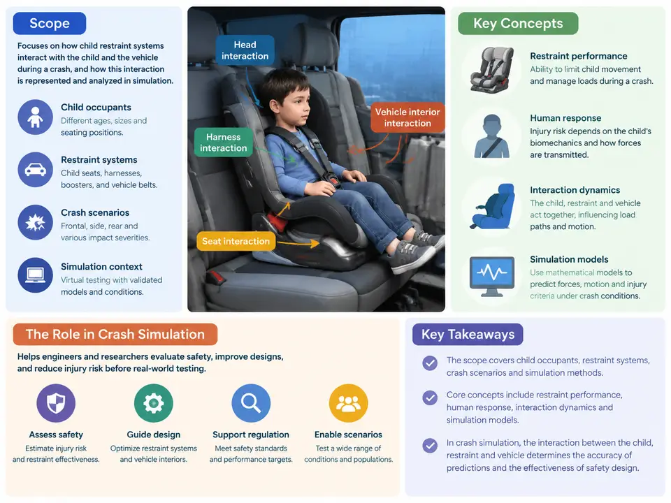
Child occupant safety is one of the most demanding subdomains of vehicle crashworthiness engineering. Unlike an adult occupant, a child is not a scaled-down adult: the head is proportionally larger and heavier, the neck is weaker, the pelvis is immature, and the rib cage is far more compliant. These biomechanical differences mean that the restraint system — whether a rear-facing infant seat, a forward-facing child restraint, or a belt-positioning booster — does not simply "hold" the child. It interacts with the child's body, with the vehicle seat, with the seat belt geometry, and with the vehicle's deceleration pulse in a tightly coupled way. This course is about modeling and analyzing that interaction inside a crash simulation environment.
What This Course Covers
The scope spans the full simulation workflow for child occupant restraint interaction: restraint system architecture, child anthropomorphic test devices (ATDs) and human body models, finite element (FE) modeling of child seats and belt routing, contact definition, loading and boundary conditions, output interpretation, and validation against physical sled or full-vehicle tests. The course treats both regulatory and consumer-rating load cases (for example, FMVSS 213, ECE R44/R129, and Euro NCAP frontal and side impact protocols) as the driving requirements that shape how a model must be built and judged.
Three questions frame every chapter. First, what is the physical interaction we are trying to capture — belt-to-shoulder contact, shell-to-vehicle-seat compression, head-to-shell clearance, ISOFIX anchor load paths? Second, how is it represented numerically — which contacts, materials, joints, and kinematic constraints carry that interaction? Third, how do we know the representation is credible — which signals, corridors, and injury criteria tell us the model behaves like the real system?
Key Concepts and Terminology
Several concepts recur throughout the course and deserve precise definition up front.
- Child restraint system (CRS): the seat, shell, harness, padding, and attachment hardware that together restrain the child. In simulation it is usually a deformable FE assembly, not a rigid body.
- Installation mode: the way the CRS is fixed to the vehicle — ISOFIX/LATCH rigid or flexible attachments, seat belt routing, support leg, or top tether. Installation mode changes the load path and therefore the whole response.
- Belt–child interaction: the contact and friction between the harness or vehicle belt and the child's body. This is where most of the restraint force is transmitted and where modeling errors most often appear.
- Injury criteria: quantitative measures such as HIC (Head Injury Criterion), neck tension/compression and Nij, chest deflection, and abdominal pressure. These are the outputs that determine pass/fail.
- Corridor and sled pulse: the prescribed deceleration time history applied at the sled or vehicle structure; the model's response is judged against measured corridors.
The Role of Restraint Interaction in Crash Simulation
Why is "interaction" the central word? Because a child restraint is not a passive container. During a frontal impact the vehicle decelerates, the CRS shell rotates forward, the harness loads the child's shoulders and pelvis, the child's head moves relative to the shell, and the shell itself may contact the vehicle seat back or the front seat. Each of these is a coupled contact problem. If the simulation models the CRS as a rigid body, or omits friction at the harness, or uses a single-point belt instead of a routed belt, the predicted head excursion and neck load can be wrong by a large margin — often in the non-conservative direction.
The figure below shows the interaction chain that this course builds around: from the vehicle deceleration input, through the CRS attachment and shell, into the harness and child body, and out to the injury-relevant outputs. It is a signal-and-load-path view, not a step list — the point is to see which physical interfaces must be represented and where the model's credibility is decided.
How the Course Approaches the Problem
The course is organized around building a model that can be trusted, not merely one that runs. That means every modeling decision is tied to a physical interface and to an observable output. For example, when we discuss harness modeling, we will not just say "define a belt." We will look at a concrete case: a forward-facing CRS with a five-point harness, a 3-year-old ATD, and a 50 km/h frontal sled pulse. The harness is modeled as a seatbelt element set with a defined routing through D-rings and buckle, a friction coefficient of roughly 0.3 at the shoulder, and a retractor or pretensioner characteristic if present. The expected observable is the shoulder belt force time history and the resulting chest deflection; a typical failure symptom is a belt that slides off the shoulder because the friction or routing is wrong, producing an unrealistically low chest load and a head excursion that looks "good" for the wrong reason.
Similarly, when we cover CRS-to-vehicle-seat contact, the practical question is whether the seat cushion and back are modeled with realistic stiffness and friction. A common error is to use a rigid seat, which suppresses shell rotation and under-predicts head excursion. The course will show how to check this by comparing shell rotation angle and head excursion against a known sled test corridor.
What You Should Be Able to Do After This Chapter
By the end of this overview you should be able to state, in your own words, why child occupant restraint interaction is a coupled contact problem rather than a simple restraint problem; identify the main interfaces in the interaction chain (vehicle pulse, attachment, shell, harness, child body, vehicle seat) and the output each one influences; and explain why a rigid or oversimplified representation of any one interface can bias the injury prediction. These ideas are the foundation for the modeling, loading, and validation work in the chapters that follow.
The remaining chapters move from this conceptual map into concrete model construction: restraint geometry and attachment, ATD and HBM selection, belt and contact definition, load case setup, output extraction, and correlation against test data. Each will return to the interaction chain above, so that the model you build is traceable from input pulse to injury output at every step.