1. VTC load case fundamentals
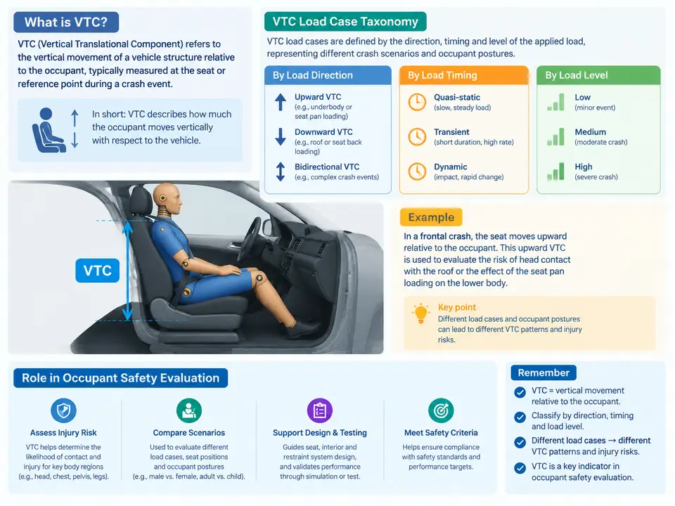
In occupant safety engineering, a Vehicle Test Configuration (VTC) is the fully specified, reproducible description of a single physical or virtual crash event: the barrier or impactor, the impact velocity and angle, the vehicle state (mass, ride height, steering angle, tire pressure), the restraint configuration (belt routing, pretensioner and load-limiter settings, airbag deployment state), and the occupant anthropometry and seating position. A VTC is not merely "a crash test"; it is the atomic unit of comparability. Two results can only be compared, trended, or used to justify a design decision when their VTCs are identical or the differences are explicitly quantified.
The distinction between a VTC and a load case is worth fixing early. The load case is the abstract loading condition — for example, "50 km/h full-frontal rigid barrier impact." The VTC is the concrete instantiation of that load case for a specific vehicle program, including all boundary conditions that materially affect occupant response. In practice, engineers often use the terms interchangeably, but the discipline of separating them prevents a common failure: assuming that two tests share a load case when their VTCs actually differ in ride height, bumper engagement, or restraint calibration.
Load Case Taxonomy
VTCs are organized along three orthogonal axes: impact direction, impact severity and barrier type, and occupant/restraint state. The first two are largely dictated by regulation and consumer rating; the third is where most engineering judgment lives.
| Axis | Categories | Typical VTC parameters |
|---|---|---|
| Impact direction | Frontal, oblique frontal, side, rear, rollover, pedestrian/VRU | Impact angle (0°, 15°, 30°, 90°), yaw rate, barrier face geometry |
| Severity & barrier | Full rigid barrier, offset deformable barrier (ODB), mobile progressive deformable barrier (MPDB), pole, moving deformable barrier (MDB) | Velocity (e.g., 50, 56, 64 km/h), barrier stiffness, overlap percentage (40%, 25%, 100%) |
| Occupant & restraint state | ATD size (5th percentile female, 50th percentile male), seating position, belt use, out-of-position (OOP) | H-point coordinates, seat track position, recline angle, pretensioner/load-limiter level, airbag suppression flag |
A complete VTC identifier therefore reads like a compound label, for example: FR-ODB-64-40-DB50M-BELT-L2 — frontal, offset deformable barrier, 64 km/h, 40% overlap, 50th percentile male dummy, belted, load-limiter level 2. This naming convention is not cosmetic; it is what allows a test matrix to be queried, deduplicated, and audited.
Why the VTC Governs Occupant Injury Evaluation
Occupant injury metrics — HIC15, chest deflection, Nij, femur force, and the various injury risk curves built on them — are conditional quantities. A HIC value of 700 means something different at 50 km/h full-frontal than at 64 km/h ODB, and something different again when the occupant is a 5th percentile female seated at full-forward track. The VTC supplies the conditioning context that makes the number interpretable. Strip the VTC away and the metric becomes a number without a referent.
This has a direct practical consequence for evaluation workflow. When a restraint calibration change is proposed — say, lowering the load-limiter force from 4.0 kN to 3.5 kN — the evaluation must hold the VTC fixed and vary only the restraint parameter. If the ride height or bumper stiffness also changed between the baseline and the candidate, the observed chest deflection delta cannot be attributed to the load limiter. Isolating variables is the entire point of a controlled VTC matrix.
Reading a VTC Through the Signal Chain
The most reliable way to internalize how a VTC drives occupant outcome is to trace the causal chain from the prescribed boundary condition to the measured injury metric. The figure below shows this chain for a frontal ODB VTC, with the intermediate physical quantities that each stage produces and the points where a VTC parameter enters.
The chain makes a subtle but important point: VTC parameters do not all enter at the same stage. Ride height and steering angle modify the vehicle kinematics; barrier stiffness and overlap modify the deceleration pulse shape; load-limiter and pretensioner settings modify occupant loading directly; ATD size and seat position modify how the occupant responds to that loading. A change at any stage propagates downstream, but the sensitivity differs. This is why a well-constructed VTC matrix varies one stage at a time where possible, and why a full-factorial matrix across all fields is usually infeasible and unnecessary.
Constructing a Minimal VTC Record
For practical work, a VTC should be captured as a structured record rather than free text. The following is a minimal but complete example for a frontal ODB case, with illustrative values that are representative of a mid-size passenger car program. These values are teaching examples, not measured results from a specific vehicle.
vtc_id:            FR-ODB-64-40-DB50M-BELT-L2
impact_direction:  frontal (0 deg)
barrier:           offset deformable, honeycomb face, 40% overlap
velocity_kmh:      64
vehicle_mass_kg:   1580 (incl. ATD and instrumentation)
ride_height_mm:    520 (front axle, nominal)
steering_angle_deg: 0
tire_pressure_kpa: 240
restraint:
  belt:           3-point, pretensioner = pyrotechnic, load_limiter = 3.5 kN
  airbag:         driver frontal, 60 L, vented, deployment confirmed
occupant:
  atd:            Hybrid III 50th percentile male
  seat_track_mm:  120 (mid)
  recline_deg:    25
  h_point_mm:     (x=1250, y=-350, z=520) vehicle coordinate frame
measurements:     head accel (3-axis), chest accel, chest deflection,
                  femur load (L/R), belt force, airbag pressure
criteria:         HIC15 <= 700, chest defl <= 50 mm, femur <= 10 kN
Two conventions in this record deserve explicit statement because they recur throughout the course. First, the vehicle coordinate frame is defined as x forward, y to the left, z upward, origin at the front axle centerline at nominal ride height. All H-point and intrusion values in this course use this frame unless a figure states otherwise. Second, positive deflection for chest and femur is defined as compression/compressive load; sign conventions for acceleration follow the sensor mounting axis, which must be recorded per channel.
Common Pitfalls in VTC Definition
- Omitting restraint calibration state. A VTC that says "belted" but not the load-limiter level is not reproducible; two builds with different limiter settings will produce different chest deflection under an otherwise identical VTC.
- Conflating nominal and as-tested vehicle mass. Adding ATD, instrumentation, and ballast changes the deceleration pulse. Record the as-tested mass, not the curb mass.
- Ignoring seat track and recline. These shift the occupant relative to the airbag and belt geometry and can dominate chest and neck metrics in OOP-adjacent cases.
- Treating the barrier as a constant. Deformable barrier face condition (temperature, prior impacts, honeycomb crush history) affects the pulse; a used barrier is not the same VTC as a fresh one.
With the VTC defined, its taxonomy established, and its role in conditioning injury metrics made explicit, the foundation is in place for the load-case-specific evaluation methods that follow. The key takeaway for this chapter is procedural: every injury number in occupant safety carries an implicit VTC, and the quality of any evaluation depends on how rigorously that VTC is specified, recorded, and held constant.