1. Side pole far-side and oblique crash inj
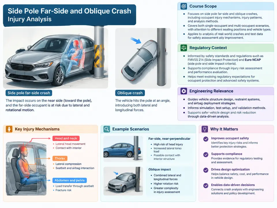
Side pole far-side and oblique crash injury analysis sits at the intersection of structural crashworthiness, occupant kinematics, and restraint system design. It addresses a class of impact scenarios in which the vehicle's principal energy-absorbing structure is either bypassed or loaded in a direction it was not primarily designed for. This opening chapter establishes what the course covers, why these two scenarios are treated together, how they appear in regulation and consumer testing, and why they remain among the most demanding problems in occupant protection engineering.
Defining the Two Scenarios
A side pole impact occurs when a vehicle strikes a narrow, rigid object—typically a utility pole, tree, or signpost—with its side. The contact patch is small, often 250–350 mm wide, so the load is concentrated over a short longitudinal span of the door and B-pillar region. Because the pole does not deform appreciably, the vehicle must absorb nearly all the kinetic energy through local crushing of the door structure, rocker, roof rail, and floor. The resulting intrusion can be severe even at moderate speeds.
The term far-side refers to the occupant seated on the side opposite the impact. In a pole strike on the driver's side, the front passenger is the far-side occupant. That occupant is not directly loaded by the door but is instead accelerated laterally across the cabin by the vehicle's own yaw and lateral deceleration. The far-side occupant's injury risk is dominated by head excursion into the opposite interior, torso interaction with the center console, and, in some cases, ejection through the far window if the glazing or restraint fails.
An oblique crash is a frontal impact with a significant lateral component, typically defined in test protocols as a barrier angled 15° or 30° from the vehicle's longitudinal axis, or as a moving deformable barrier striking at an angle. The occupant loads the restraint system off-axis: the seat belt geometry, airbag deployment path, and seat structure all experience combined frontal and lateral loading. Small overlap and oblique frontal impacts are related but distinct; the oblique case specifically emphasizes the angled loading direction and the resulting occupant rotation.
Why These Scenarios Are Grouped
Although the loading paths differ, the two scenarios share a common engineering thread: the occupant's motion is not aligned with the primary restraint design direction. In a flat frontal crash, the belt and airbag are tuned for a predominantly longitudinal occupant trajectory. In a flat side impact, the near-side occupant is managed by side airbags and door trim. Pole far-side and oblique crashes both produce occupant motion with a strong lateral or rotational component that the primary restraint was not optimized for. Grouping them lets the course treat occupant kinematics, restraint interaction, and injury metrics as a unified analytical problem rather than two disconnected test procedures.
Regulatory and Consumer-Testing Context
Regulatory treatment of these scenarios varies by jurisdiction and has evolved considerably. The table below summarizes the principal references an analyst should know.
| Reference | Scenario | Key characteristics |
|---|---|---|
| FMVSS 214 (US) | Side impact, moving deformable barrier and pole | Includes a rigid pole test at 32 km/h (20 mph) with a 254 mm diameter pole; evaluates near-side occupant in a specified seating position |
| UN R135 (Europe) | Side pole impact | Rigid pole at 32 km/h, 75° impact angle; focuses on near-side occupant protection and door integrity |
| Euro NCAP side pole | Side pole, far-side assessment | Adds far-side occupant monitoring and, in later protocols, far-side countermeasure evaluation |
| IIHS side and moderate overlap | Side barrier, oblique-adjacent frontal | Higher-energy side barrier; moderate overlap frontal provides context for off-axis restraint behavior |
| Oblique frontal protocols | Angled frontal barrier or MDB | 15°/30° angled loading; evaluates restraint coupling and occupant rotation under combined loading |
Two points deserve emphasis. First, most regulatory pole tests historically evaluated the near-side occupant; far-side protection has been driven more by consumer testing and research than by prescriptive regulation. Second, oblique frontal testing remains largely a research and consumer-rating activity rather than a harmonized regulatory requirement, which means the analyst must often work from protocol documents and published rating criteria rather than a single legal standard.
Engineering Relevance
These scenarios matter because they expose failure modes that are easy to miss in conventional testing. In a pole impact, the small contact area means the door's beltline and rocker must carry concentrated load; if the B-pillar buckles or the door separates, intrusion into the occupant compartment rises sharply. For the far-side occupant, the absence of a dedicated side airbag on that side means the center console, seat structure, and far-side trim become the effective restraint surface—an unintended and often poorly optimized load path.
In oblique crashes, the occupant's torso rotates relative to the belt. This can cause the shoulder belt to slip off the shoulder, reduce belt–torso coupling, and allow greater forward and lateral excursion. Airbag timing tuned for a flat frontal event may deploy the bag into a path the occupant is no longer following. The result is a mismatch between restraint geometry and occupant trajectory that shows up as elevated head and chest injury metrics even when the structural deformation looks acceptable.
From a design standpoint, the practical questions are concrete: How much lateral head excursion does the far-side occupant experience, and does it contact the far door or B-pillar? Does the center console present a hard, sharp surface? In the oblique case, does the belt remain on the shoulder through the event, and does the airbag maintain coverage as the torso rotates? Answering these requires a combination of sled testing, full-vehicle testing, and CAE correlation—the analytical workflow this course develops.
Course Scope and Analytical Workflow
The course proceeds from the physical scenario to the measurement and judgment layer. The figure below maps the analytical chain that connects an impact event to an injury-relevant conclusion, and it is the backbone for the chapters that follow.
The chain runs from scenario definition, through occupant kinematics and restraint interaction, to measurement and injury assessment. Each stage has its own data requirements and its own sources of uncertainty. A pole test may show acceptable structural deformation while the far-side occupant's head excursion still exceeds a containment threshold; an oblique sled may show a well-timed airbag while the belt has slipped off the shoulder. The analyst's job is to keep the chain intact—to ensure that the measured quantity actually corresponds to the injury mechanism being evaluated.
What the Analyst Must Be Able to Do
By the end of the course, a practitioner should be able to select the appropriate test or simulation configuration for a given scenario, interpret occupant and structural measurements in light of the underlying kinematics, and judge whether a countermeasure—far-side airbag, center console redesign, belt geometry change, or airbag re-timing—actually addresses the failure mode. The course emphasizes the reasoning behind each measurement rather than the mechanics of running a particular software package, because the tools change while the physics does not.
A final caution for the chapters ahead: these scenarios are sensitive to small changes in setup. Pole diameter, impact angle, seat position, belt routing, and occupant size all shift the outcome. Any result must be reported with its configuration attached, and any comparison must hold configuration constant. That discipline begins here, with a clear definition of scope and a shared vocabulary for the scenarios the course will analyze.