1. Neck Load Calculation from Head Mass and
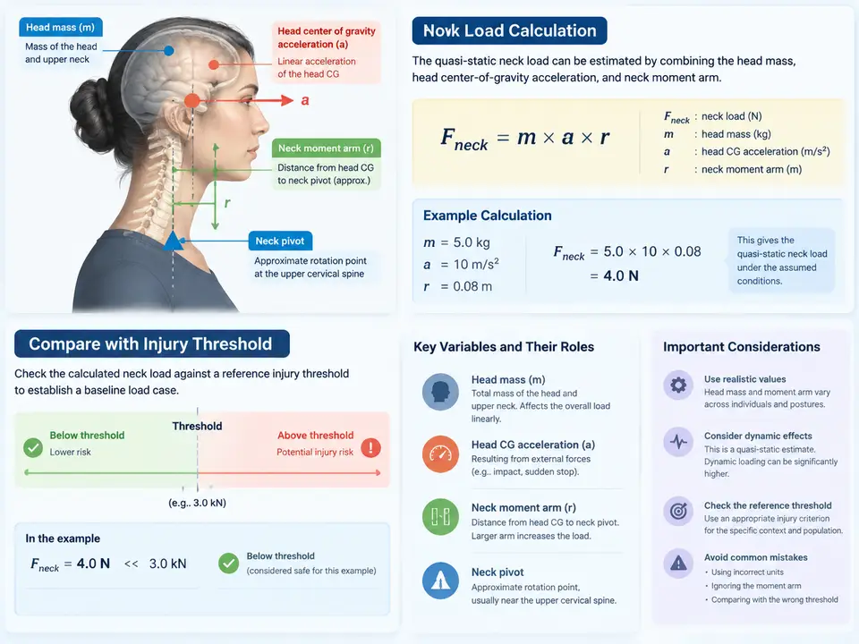
Why a Baseline Quasi-Static Neck Load Matters
Before any Nij (Neck Injury Criterion) computation can be trusted, the analyst needs a defensible baseline load case: a single, hand-checkable number that represents the neck's bending demand under a defined acceleration. This baseline serves three purposes. First, it validates the sign conventions and unit handling that later time-history processing will depend on. Second, it gives a sanity anchor — if a full sled simulation later reports a peak upper-neck moment an order of magnitude away from the baseline, something in the model or the post-processing is wrong. Third, it produces a first-order comparison against a reference injury threshold, which tells the engineer whether the load case is even worth pursuing in detail.
The quasi-static assumption is deliberate. By treating the head as a rigid mass whose center of gravity (CG) accelerates uniformly, and by ignoring the inertial lag of the neck soft tissue, we obtain a conservative, closed-form estimate. This is not a substitute for a validated finite element or multi-body model; it is the calculation that must agree with such a model before the model is believed.
Defining the Geometry and Sign Convention
All quantities below use a right-handed SAE-style occupant coordinate system: +X forward (direction of travel for a frontal impact), +Y to the occupant's left, +Z upward. Neck bending moment is reported about the +Y axis, with positive moment corresponding to forward head rotation (flexion). This convention must be stated once and held constant through the calculation, the SVG, and any later time-history work; a sign flip here is the single most common source of a wrong Nij.
The three inputs are:
- Head mass
m_h— the mass of the head alone, excluding the neck. For a 50th-percentile male Hybrid III representation, a commonly used value ism_h = 4.54 kg. - Head CG acceleration
a_x— the translational acceleration of the head center of gravity along+X. In a frontal pulse the head decelerates relative to the vehicle, so a rearward-directed inertial load acts on the neck; we will carry the magnitude and apply the direction explicitly. - Neck moment arm
d— the vertical distance from the head CG to the upper-neck load cell (the occipital condyle / C1 level in a physical dummy). A representative value isd = 0.065 m.
The Quasi-Static Load Equations
The inertial force generated by the head mass is simply Newton's second law applied at the CG:
F_inertial = m_h * a_x [N]Because this force acts at the head CG, which sits a vertical distance d above the neck load cell, it produces a bending moment at the neck:
M_neck = F_inertial * d = m_h * a_x * d [N·m]Two practical cautions apply. First, a_x must be in m/s²; if the source data is in g, multiply by 9.81. Second, the moment arm d is a vertical offset, so only the horizontal (X) component of acceleration contributes to the flexion/extension moment in this simplified model. A vertical acceleration component would produce a shear/axial load, not a bending moment about Y, and is outside the scope of this baseline.
Worked Baseline Calculation
Take a frontal deceleration pulse with a quasi-static plateau of a_x = 15 g. Convert to SI: a_x = 15 × 9.81 = 147.15 m/s².
m_h = 4.54 kg
a_x = 147.15 m/s^2
d   = 0.065 m

F_inertial = 4.54 * 147.15        = 668.06 N
M_neck     = 668.06 * 0.065       = 43.42 N*m
The inertial force is roughly 668 N and the resulting neck bending moment is approximately 43.4 N·m. Note that the force direction is rearward (the head lags the decelerating torso), which in our convention produces a moment that resists forward flexion — i.e., an extension-directed demand during the deceleration phase. For the baseline comparison we use the magnitude and record the direction explicitly.
Comparing Against a Reference Injury Threshold
For a first-order check, compare the computed moment against a published critical intercept. Using the widely cited Nij normalization constants for a mid-size male, the critical moment about the Y axis is M_crit = 88 N·m (extension) and M_crit = 88 N·m (flexion) in the simplified symmetric form often used for screening. The ratio is:
M_neck / M_crit = 43.42 / 88 = 0.49A ratio near 0.49 indicates the baseline load case sits at roughly half the critical moment. This is a screening result, not an injury prediction: it tells the engineer the case is in a regime where detailed Nij time-history analysis is warranted, and it provides the anchor against which the peak from a full pulse (the subject of the next case) can be checked. If the ratio had come out above ~1.0, the geometry or mass inputs would need re-examination before proceeding.
m_h, d, and sign convention should be reused unchanged so that the baseline and the peak are directly comparable.Visualizing the Load Path
The diagram below shows how the three inputs combine into the neck moment and how that moment is compared to the critical threshold. It is a parameter-relationship view, not a process flow: the head CG acceleration and mass feed the inertial force, the moment arm converts force to moment, and the moment is placed on a ratio scale against M_crit.
Verification and Common Failure Symptoms
To verify the baseline, re-derive the moment from the force and arm independently and confirm the ratio. A quick dimensional check: kg × m/s² = N, and N × m = N·m, so the units close. If your spreadsheet returns a moment in the hundreds of N·m for a 15 g pulse, the most likely cause is a unit error — acceleration left in g while the mass is in kg, or the moment arm entered in millimetres instead of metres. If the ratio comes out negative, the sign convention was applied inconsistently between the force direction and the moment definition. If the ratio is implausibly small (below ~0.1), check that d was not entered as the full head height rather than the CG-to-load-cell offset.
Record the baseline as a named case — inputs, computed force, computed moment, threshold, and ratio — so that the time-history Nij work that follows can be validated against it. The baseline is the reference the rest of the diagnostic sequence is measured against.