1. Restraint system simulation landscape
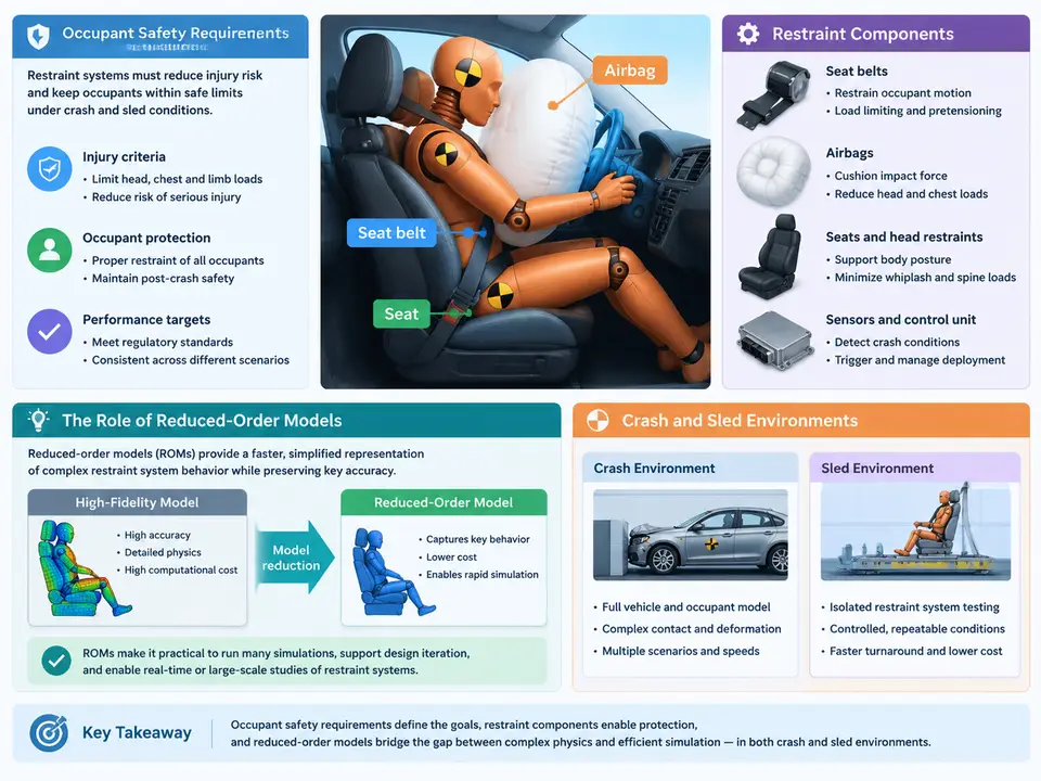
Occupant safety engineering is fundamentally a problem of managing energy and timing. In a frontal impact at 56 km/h, a vehicle decelerates from roughly 15.6 m/s to rest in about 100–120 ms. The occupant, however, continues forward at the original velocity until the restraint system intervenes. The restraint system's job is to couple the occupant to the vehicle's deceleration pulse as gently and as early as physically possible, keeping loads on the chest, head, neck, and pelvis within injury-assessment reference values while preserving the survival space of the occupant compartment. Simulation is the primary tool for designing that coupling, and reduced-order models (ROMs) are increasingly the tool that makes restraint design iteration fast enough to be practical.
Regulatory and Rating Requirements That Drive the Models
Restraint simulation does not exist in a vacuum; it is calibrated against test protocols. In the United States, FMVSS 208 defines frontal barrier and sled tests with unbelted and belted occupants, including the 5th-percentile female and 50th-percentile male dummies. In Europe, UN R94/R137 and Euro NCAP frontal offset and mobile progressive deformable barrier tests add structural intrusion and a broader occupant matrix. Consumer-rating programs such as Euro NCAP, C-NCAP, and IIHS further push restraint tuning toward real-world injury metrics: HIC15, chest deflection, chest acceleration (3 ms clip), neck tension and moment, and femur loads.
Each requirement translates into a simulation load case with a defined boundary condition. A full-vehicle crash model resolves the vehicle structure, but a sled model replaces the vehicle with a prescribed acceleration pulse applied at the seat and floor attachment points. Sled simulation is where most restraint tuning happens because it isolates the occupant-restraint system from structural crash variability, runs in minutes rather than hours, and maps directly to the physical sled test used for certification.
The Restraint Component Set
A modern frontal restraint system is a chain of interacting components, each with distinct modeling fidelity needs:
- Seat belt system — webbing (load-limited by construction and stitch patterns), retractor with spool-out and locking behavior, pyrotechnic pretensioner, buckle pretensioner, and force limiter. Belt routing over the shoulder and lap, and the friction between webbing and dummy surface, dominate chest loading.
- Airbags — driver and passenger frontal airbags, side thorax and curtain airbags, knee airbags. Inflation is driven by a pyrotechnic inflator whose mass-flow and temperature history determine bag pressure and venting.
- Seat structure — cushion and backframe stiffness, recliner behavior, and anti-submarining geometry. The seat is the reaction surface for the belt and the occupant's pelvis.
- Steering column — collapsible column stroke and energy absorption, which sets the driver's forward excursion limit.
- Sensing and deployment logic — crash pulse sensing, deployment timing, and adaptive restraint decisions (dual-stage inflators, belt force limiting).
In a full finite-element occupant model, each of these is meshed in detail: the belt as a shell or seatbelt element chain, the airbag as a folded membrane with a uniform-pressure or corpuscular-particle (CPM) gas model, and the dummy as a validated multi-body or FE human body model. That fidelity is necessary for final validation, but it is expensive: a single frontal sled run with a detailed dummy and folded airbag can take hours, and design-of-experiments studies over dozens of parameters become prohibitive.
Where Reduced-Order Models Fit
Reduced-order models trade geometric and contact detail for speed while preserving the input–output behavior that matters for the design question. In restraint simulation, ROMs appear in three distinct roles:
- Component surrogates. An airbag's inflation and venting behavior can be represented by a calibrated pressure–volume–time characteristic or a small set of lumped parameters rather than a folded membrane. A belt force limiter becomes a piecewise force–displacement curve. These surrogates are fitted to detailed FE or test data and then substituted into the system model.
- Occupant surrogates. Multi-body models of the dummy (rigid bodies connected by joints and force elements) run orders of magnitude faster than FE human body models and are adequate for restraint parameter sweeps, provided the injury metrics of interest are mapped through validated transfer functions.
- System-level metamodels. A response-surface or Gaussian-process model trained on a designed set of sled simulations predicts injury metrics as a function of restraint parameters (pretensioner timing, force-limiter level, vent size, bag pressure). This is the ROM that enables optimization and robustness studies.
Crash Versus Sled: Two Environments, Two Model Contracts
The distinction between crash and sled environments is not merely geometric; it changes what the model must reproduce. In a full-vehicle crash, the boundary condition is the barrier impact and the resulting structural crush; the occupant model receives a computed deceleration at the seat mounts, and structural intrusion into the occupant compartment is an output that feeds back into restraint performance. In a sled, the deceleration pulse is an input, prescribed from a vehicle crash pulse or a regulatory corridor, and intrusion is either absent or represented by a simplified moving barrier.
This means a sled ROM must be validated against sled tests, not crash tests, and its pulse must be documented precisely: the acceleration–time history, its integration to velocity change (Δv), and the filter class applied (e.g., SAE J211 CFC 60 for occupant response, CFC 180 for structural). A common failure mode in ROM development is fitting a surrogate to a pulse that was filtered differently from the validation data, producing a model that looks correct in isolation but mispredicts timing by 5–10 ms — enough to shift peak chest deflection by several millimeters.
What a Working ROM Pipeline Looks Like
A representative workflow for a frontal sled restraint study proceeds as follows. First, a validated detailed sled model is assembled: a prescribed pulse (for example, a 56 km/h, 120 ms pulse with Δv = 15.6 m/s, filtered at CFC 60), a 50th-percentile male FE dummy, a detailed folded driver airbag with a pyrotechnic inflator, and a belt model with retractor and force limiter. This model is correlated against a physical sled test at a baseline configuration; correlation targets are peak chest deflection within ±3 mm, HIC15 within ±10%, and head excursion timing within ±5 ms.
Next, the detailed components are replaced by surrogates one at a time, and the surrogate is re-correlated. The airbag, for instance, is replaced by a pressure–volume curve extracted from the detailed run, with vent area and inflator mass flow retained as parameters. The belt force limiter becomes a piecewise-linear force–displacement element. Each substitution is accepted only if the occupant response stays within the correlation tolerance across the pulse matrix, not just the baseline pulse.
Finally, a design of experiments is run on the surrogate model. A typical parameter set might include pretensioner firing time (10–25 ms), force-limiter level (2.5–4.5 kN), airbag vent diameter (25–40 mm), and inflator output scaling (0.9–1.1). A Latin hypercube of 60–100 runs on the multi-body surrogate completes in a few hours, and the resulting response surface is used to identify the parameter combination that minimizes chest deflection while keeping head excursion inside the survival space. The optimum is then verified once in the detailed FE model before hardware testing.
Reading the Landscape Correctly
The practical value of ROMs in restraint simulation is not that they replace detailed models, but that they restructure the design loop. Detailed FE answers "what happens in this exact configuration"; ROMs answer "how does the outcome move as I change the design." The engineer's task is to keep the two connected: every surrogate must trace back to a validated detailed model or test, every metamodel must carry its training bounds, and every sled pulse must be documented with its Δv and filter class. When those contracts are respected, a restraint team can evaluate hundreds of design variants in the time a single detailed run used to take — and arrive at the physical sled test with a configuration that is already close to optimal.