1. Finite element mesh fundamentals
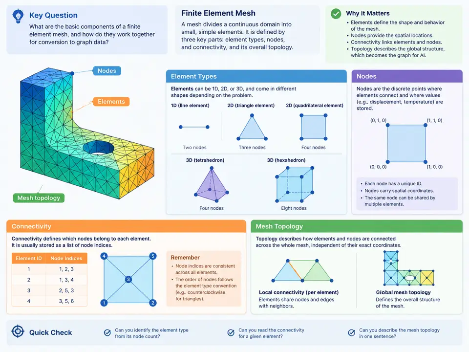
Converting a finite element (FE) mesh into graph data for AI begins with a precise reading of what the mesh actually is. An FE mesh is not merely a collection of coordinates; it is a structured discretization in which every element carries a type, a node ordering, and a set of topological relationships to its neighbors. Before any graph tensor can be built, the conversion pipeline must recover these relationships faithfully. This chapter establishes the vocabulary and the structural model that every later conversion step depends on.
Nodes: The Atomic Entities
A node is the fundamental geometric entity of a mesh. In a typical solver input deck, each node is defined by an identifier and a coordinate triple. For example, a Nastran-style bulk data entry looks like this:
GRID, 101, 0.0, 0.0, 0.0
GRID, 102, 1.0, 0.0, 0.0
GRID, 103, 1.0, 1.0, 0.0
GRID, 104, 0.0, 1.0, 0.0
Node IDs are labels, not indices. They may be sparse, non-contiguous, or reordered by the mesher. A conversion pipeline must therefore build an explicit ID-to-index mapping before constructing any adjacency structure. In graph terms, nodes become vertices, and the coordinate triple becomes a node feature vector — typically the three spatial coordinates, optionally augmented with displacement, temperature, or other field values if the dataset is simulation-aware.
It is important to distinguish geometric nodes from graph nodes. In a pure element-adjacency graph, graph nodes correspond one-to-one with FE nodes. In a dual graph or element-centric graph, graph nodes correspond to elements instead. The choice of graph node semantics is a design decision that must be fixed before conversion, because it determines the shape of every downstream tensor.
Element Types and Node Ordering
Element type determines how many nodes an element references and in what order. The ordering is not arbitrary: it encodes the element's local coordinate system and is used by shape functions, integration rules, and face definitions. Common families include:
- Line elements (2-node bar, 3-node beam) — used for trusses, frames, and reinforcement.
- Shell elements (3-node triangle, 4-node quad, 6-node triangle, 8-node quad) — used for plates and thin-walled structures.
- Solid elements (4-node tetrahedron, 8-node hexahedron, 10-node tet, 20-node hex) — used for volumetric domains.
For conversion, the critical facts are the node count per element and the canonical ordering. A 4-node quad, for instance, is conventionally ordered counter-clockwise around its normal. If a converter assumes a different ordering than the source deck, face extraction and edge construction will silently produce wrong adjacency. The safest practice is to store the element type as an explicit categorical feature and to keep the raw connectivity tuple intact rather than re-sorting it.
Connectivity: The Core Data Structure
Connectivity is the mapping from each element to its ordered list of node IDs. In memory, this is usually a two-dimensional array of shape [num_elements, nodes_per_element], padded or ragged depending on whether mixed element types are present. A minimal connectivity table for a two-element quad mesh might be:
ELEMENT  TYPE   N1   N2   N3   N4
1        QUAD4  101  102  103  104
2        QUAD4  102  105  106  103
From this table alone, a converter can derive edges, faces, and element adjacency. The connectivity table is the single source of truth for topology; coordinates are only needed for geometric features. This separation matters because it allows the same connectivity to be reused across multiple simulation snapshots that share a mesh but differ in field results.
Mesh Topology: Derived Relationships
Topology is the set of relationships that connectivity implies. The three most important derived structures for graph conversion are:
- Node adjacency — which nodes share an element edge. This yields the edge list of a node-centric graph.
- Element adjacency — which elements share a face or edge. This yields the edge list of an element-centric (dual) graph.
- Incidence — the bipartite relation between nodes and elements, often stored as a sparse incidence matrix.
Consider the two-quad example above. Nodes 102 and 103 are shared by both elements, so the node adjacency graph contains the edge (102, 103) contributed by element 1 and again by element 2. A correct converter deduplicates such edges and records the multiplicity as an edge feature, since duplicated edges indicate shared boundaries and are meaningful for message passing. Element adjacency, by contrast, contains a single edge between element 1 and element 2 because they share the face defined by nodes 102 and 103.
(min(u,v), max(u,v)). Store the count of contributing elements as an edge weight; this preserves boundary information that naive deduplication would discard.From Mesh to Graph: The Structural Mapping
The figure below summarizes how the four mesh concepts map onto graph structures. It is worth reading left to right: raw deck entities become typed arrays, which in turn generate the adjacency structures consumed by graph neural networks.
Practical Conversion Considerations
Three issues recur in real conversion work. First, mixed element types break fixed-width connectivity arrays. A mesh containing both QUAD4 and TRIA3 elements cannot be stored as a rectangular array without padding. The standard solution is to group elements by type, build one homogeneous block per type, and concatenate the resulting edge lists with a type tag. Second, node ID gaps require an explicit remapping. If the deck uses IDs 1001–1050 and 2001–2050, the graph must use dense indices 0–99, with the original IDs retained as a feature or lookup table. Third, orientation and normals matter for shells. Two adjacent quads may share an edge but have opposite winding; the converter should detect this by comparing the shared edge direction and record a sign flag rather than silently merging the edges.
A useful verification step after conversion is to check Euler-style invariants. For a closed 2D manifold mesh, the relation V − E + F = 2 should hold for the node-edge-face complex, where F counts faces. If the converted graph reports a different value, the edge extraction has likely dropped or duplicated boundary edges. Running this check on a small hand-built mesh — such as the two-quad example above, where V = 6, E = 7, F = 2, giving 6 − 7 + 2 = 1 for an open patch — quickly reveals whether the topology extraction is consistent with the expected boundary condition.
What the Converter Must Preserve
By the end of this stage, the conversion pipeline should hold four artifacts: a dense node index with coordinates, a per-element type label with its ordered node tuple, a deduplicated undirected edge list with multiplicity weights, and an element-adjacency list for dual-graph use. These four artifacts are sufficient to generate any of the common graph representations used in mesh-based machine learning, and they preserve the information needed to reconstruct the original mesh if required. The next stages of the pipeline build tensors from these artifacts; the correctness of everything downstream depends on the fidelity of this first structural reading.