1. Define Validation Scope and Acceptance C
Why a Validation Plan Must Precede Any Simulation
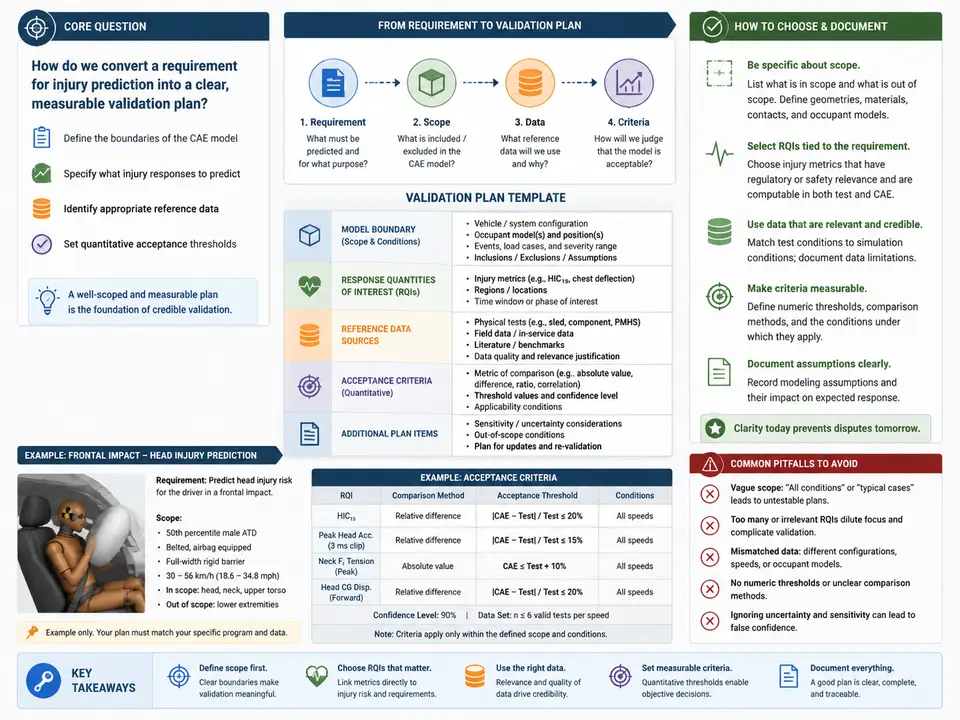
In CAE-based injury prediction, the most expensive mistake is not a bad mesh or a wrong material card — it is validating against the wrong question. A model that predicts peak von Mises stress beautifully but is asked to certify occupant rib fracture risk has been validated for the wrong response quantity. Before a single element is refined or a single material parameter is calibrated, the team must fix what the model is being asked to predict, against what it will be judged, and how close is close enough. This case builds that foundation: a written validation plan that defines the model boundary, the response quantities of interest (QOIs), the reference data sources, and quantitative acceptance thresholds.
The plan is deliberately written before any simulation evidence exists. It is a contract with the future: it prevents post-hoc threshold tuning (choosing the pass criterion after seeing the result), it makes the reference data auditable, and it gives every downstream case — mesh convergence, material traceability, correlation studies — a fixed target to aim at.
Step 1 — Anchor the Plan to a Regulatory or Design Requirement
Every validation plan starts from a requirement statement, not from the model. Take a representative requirement for a frontal-impact occupant injury model:
This statement already implies the model boundary (occupant chest/thorax region, belted, frontal loading), the QOIs (chest deflection, rib strain, an injury criterion such as a chest-deflection-based risk), and the reference source (physical sled tests). The job of the plan is to make each of these explicit, bounded, and measurable.
Step 2 — Define the CAE Model Boundary
The boundary must state what is inside the model and what is treated as a prescribed input. Ambiguity here is the most common source of invalid comparisons. A defensible boundary statement for this case:
- Included: thorax and abdomen finite element mesh, rib cage with cortical/cancellous representation, sternum, spine segment, belt webbing and retractor as a prescribed force–displacement or slip condition, and occupant positioning per the test setup.
- Excluded / prescribed: head and lower extremities (mass and inertia only), seat cushion compliance (prescribed load curve), and restraint firing timing (taken from test data, not predicted).
- Loading: barrier pulse applied as an acceleration or velocity boundary condition matching the sled pulse used in the reference test.
If the reference test used a different pulse or belt routing than the model, the comparison is invalid regardless of how good the correlation looks. The boundary statement is therefore also a checklist for the reference-data audit in the next case.
Step 3 — Select Response Quantities of Interest
QOIs must be the quantities the requirement actually depends on, and they must be extractable from both the simulation and the reference data. For this requirement, three QOIs are appropriate, each with a defined extraction location and time window:
| QOI | Definition / extraction | Reference measurement |
|---|---|---|
| Peak chest deflection | Maximum sternum-to-spine displacement, 0–120 ms | String potentiometer / chest band in sled test |
| Peak rib strain | Maximum principal strain at defined rib locations (e.g., lateral rib 5–7) | Strain-gauge instrumented ribs |
| Injury criterion (e.g., chest-deflection-based risk) | Derived from peak deflection via stated risk curve | Computed from measured deflection |
Note that the injury criterion is derived, not independently measured. The plan must state the risk curve used, because a different curve changes the acceptance outcome even with identical deflection. This is exactly the kind of hidden assumption the plan exists to expose.
Step 4 — Specify Reference Data Sources and Their Quality
Each QOI must be traceable to a named, versioned data source with known instrumentation and uncertainty. The plan should record, for each source: test ID, facility, instrumentation type and range, sampling rate, and any known limitations (e.g., chest band calibration drift, strain-gauge placement tolerance). A reference source with unknown instrumentation uncertainty cannot support a tight acceptance threshold — the threshold must be at least as wide as the combined measurement uncertainty, or the validation is testing noise.
Step 5 — Set Quantitative Acceptance Thresholds
Thresholds convert "close enough" into a pass/fail decision. Two complementary criteria are recommended: a magnitude criterion on the peak value and a shape/timing criterion on the time history.
- Peak magnitude: predicted peak within ±15% of measured peak for chest deflection; ±20% for peak rib strain (strain gauges carry larger placement uncertainty).
- Timing: time-to-peak within ±10 ms.
- Curve correlation: a correlation metric (e.g., normalized integral or coefficient of determination) above a stated value over the loading window.
These numbers are illustrative and must be justified against the measurement uncertainty from Step 4 and the decision the model supports. A model used only for ranking design variants can tolerate wider bands than one used to sign off a restraint system. The plan should state the rationale, not just the number.
Visualizing the Plan Structure
The diagram below shows how the requirement decomposes into boundary, QOIs, reference sources, and thresholds, and how each QOI is judged against its own acceptance band. It is the map the rest of the validation campaign follows.
Deliverable — Validation Plan Record
The output of this case is a single controlled document. A minimal but complete record for the example above:
| Field | Content |
|---|---|
| Plan ID / version | VP-THORAX-001, v1.0, frozen before correlation |
| Requirement | R-01 (56 km/h frontal, 50th male, chest injury) |
| Model boundary | Thorax/abdomen FE; belt, seat, firing prescribed; head/legs inertia-only |
| QOIs | Peak chest deflection; peak rib strain (lateral 5–7); chest-deflection injury risk |
| Reference sources | Sled test ID + facility + instrumentation + uncertainty per QOI |
| Acceptance thresholds | Deflection ±15% / ±10 ms; strain ±20%; risk per stated curve |
| Rationale | Thresholds ≥ measurement uncertainty; tied to design decision supported |
| Change log | Any threshold relaxation with justification and approver |
With this record frozen, every subsequent case has a fixed reference: mesh convergence must demonstrate convergence of these QOIs, material traceability must justify the inputs that drive these responses, and correlation studies are judged against these thresholds. The validation campaign now has a defined finish line rather than an open-ended search for a good-looking plot.