1. Restraint System Baseline Model Setup an
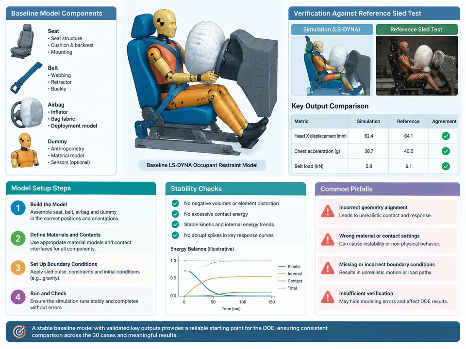
Why the Baseline Must Be Verified Before Any DOE Run
A restraint DOE is only as trustworthy as the model it perturbs. If the baseline occupant model already drifts, oscillates, or produces belt forces that never match the sled test, every subsequent factor screening and response surface will inherit that error. The task here is therefore narrow and deliberate: assemble a single, stable frontal-impact occupant model containing seat, three-point belt with retractor and pretensioner, driver airbag, and a Hybrid III 50th-percentile dummy, then confirm that its kinematics and key outputs sit within an acceptable band of a reference sled test. That verified deck becomes the immutable starting point from which belt force limiter levels, pretensioner timing, vent size, and inflator mass flow will later be varied.
Model Assembly: Objects, Connections, and Units
Build the model in a consistent unit system — the common LS-DYNA occupant convention is mm-ton-s, giving forces in newtons and stresses in MPa. Mixing kg-mm-ms with ton-mm-s is the single most frequent cause of a baseline that "looks right" but reports nonsense accelerations. Declare the system once and audit every keyword against it.
- Seat: rigid or deformable shell cushion and backrest, with a defined
*MAT_and contact to the dummy pelvis and thorax. For a baseline, a rigid seat with a compliant foam layer is sufficient and far cheaper to stabilize. - Belt: 1D seatbelt elements (
*ELEMENT_SEATBELT) routed over shoulder and lap, passing through a slipring at the D-ring and a retractor (*ELEMENT_SEATBELT_RETRACTOR) with a pretensioner (*ELEMENT_SEATBELT_PRETENSIONER). - Airbag:
*AIRBAG_SIMPLE_AIRBAG_MODELor a CV/FPM bag, with inflator mass flow defined by a*DEFINE_CURVEand venting by a*AIRBAG_...porosity or vent hole area. - Dummy: Hybrid III 50th male positioned per the sled test, with
*CONSTRAINED_...or joint stops as supplied, and accelerometers at head CG, chest, and pelvis.
Contacts matter as much as parts. The dummy-to-seat, dummy-to-belt, and bag-to-dummy interfaces should use *CONTACT_AUTOMATIC_SURFACE_TO_SURFACE with a friction coefficient near 0.3 for belt-to-clothing and a soft constraint penalty scaled to the dummy's mass. A belt that slides freely over the shoulder without friction will under-predict chest loading and make the baseline look artificially benign.
Initialization and the Sled Boundary Condition
The sled test provides a deceleration pulse. Apply it as a prescribed motion on a rigid sled platform via *BOUNDARY_PRESCRIBED_MOTION_RIGID using the measured acceleration curve integrated to velocity, or as an initial velocity plus a deceleration field. Keep the pulse definition in one curve so the DOE later changes only restraint parameters, never the crash pulse. Gravity and initial dummy posture (H-point, torso angle, head angle) must be set explicitly; a two-degree torso error can shift chest deflection by several millimetres.
Stability Checks and Output Extraction
Stability is judged before accuracy. Watch the d3hsp file for negative volumes, added mass from contacts exceeding roughly 1% of total model mass, and the energy ratio. A healthy explicit occupant run shows hourglass energy below 5% of internal energy and total energy conserved to within a few percent. If the time step collapses, the usual culprits are a thin belt element, a degenerate airbag shell, or an over-stiff contact penalty.
Extract the responses that will later become DOE outputs: head resultant acceleration for HIC36, chest deflection from the chest potentiometer, and femur loads from the upper leg load cells. Sample them at a fixed interval and store as curves so the same extraction script can be reused across all 30 cases.
Comparing Against the Reference Sled Test
Verification is a band comparison, not a single-number match. For each response, overlay the simulation curve on the measured sled curve and check three things: peak magnitude, time of peak, and overall shape. A reasonable baseline acceptance for a frontal occupant model is peak head acceleration within about ±10%, chest deflection within ±3 mm, and femur load within ±10% of the test, with peak timing within a few milliseconds. These are engineering targets, not guaranteed results — the actual numbers depend on the specific sled test and dummy build you are given.
| Response | Extraction point | Typical acceptance band | Failure symptom |
|---|---|---|---|
| HIC36 | Head CG resultant accel | ±10% of test peak | Bag too stiff or vent too small |
| Chest deflection | Chest potentiometer | ±3 mm | Belt friction or routing error |
| Femur load | Upper leg load cell | ±10% of test peak | Knee bolster contact missing |
| Belt force | Shoulder belt element | Shape match, peak ±10% | Retractor lock timing off |
Common Baseline Failures and How to Read Them
- Dummy sinks through the seat: contact penalty too soft or seat shell too thin — increase penalty scale or add a rigid backing.
- Belt force spikes at t≈0: pretensioner firing before the retractor is initialized — check the pretensioner time curve and retractor lock time.
- Airbag pushes the head backward: bag deployment too early relative to the pulse — align the inflator start time with the sled pulse onset.
- Energy not conserved: contact added mass or a runaway element — inspect the
d3hspenergy summary and the smallest time-step element.
Freezing the Starting Deck
Once the four gates in the diagram are passed, lock the deck: record the unit system, the sled pulse curve ID, the dummy build, and the exact values of every restraint parameter. This frozen file is the parent for all 30 cases. Every later variation — force limiter level, pretensioner timing, vent size, inflator mass flow — is applied as a controlled delta from this verified baseline, so any change in occupant response can be attributed to the factor under study rather than to an unstable starting model.