1. WorldSID assembly and instrumentation re
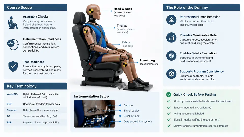
WorldSID — the World Side Impact Dummy — is a biofidelic anthropomorphic test device (ATD) developed under the auspices of the International Organization for Standardization (ISO/TC 22/SC 36) to represent a 50th-percentile adult male in lateral impact. Unlike its predecessors (EuroSID-1, EuroSID-2, SID-IIs, and the original US DOT SID), WorldSID was designed from the outset as a globally harmonized device: a single geometry, a single mass distribution, and a single instrumentation architecture intended to serve side-impact regulation, consumer rating, and research testing across markets. That harmonization ambition is precisely why assembly and instrumentation readiness matter so much. A WorldSID that is mechanically assembled but not properly instrumented, calibrated, and channel-verified is not a measurement instrument — it is a very expensive mannequin.
This course treats WorldSID as an engineering system with three interdependent layers: the mechanical assembly (skeleton, ribs, pelvis, head, neck, arms, legs, and the compliant elements that give the dummy its biofidelic response), the instrumentation layer (accelerometers, load cells, potentiometers, and angular rate sensors mounted at defined anatomical locations), and the data acquisition layer (cabling, connectors, signal conditioning, and the channel map that ties every sensor to a recorded channel). Readiness means all three layers are simultaneously correct before the dummy is seated in a sled or vehicle. A defect in any one layer — a mis-torqued rib fastener, a swapped accelerometer axis, a chafed cable — can silently corrupt an entire test and, worse, produce results that look plausible.
Why the dummy is the measurement, not the subject
In a crash test program, the vehicle or sled is the object under investigation; the WorldSID is the transducer. Every injury criterion the program reports — rib deflection, viscous criterion (VC), pelvic force, abdominal penetration, head acceleration — is derived from signals originating inside the dummy. This inversion of roles has a practical consequence: the dummy's own condition is a metrological concern, not merely a maintenance concern. A torque value on a rib screw, a cable routing decision, or a sensor's zero offset is part of the measurement chain and must be controlled with the same rigor as a load cell calibration in a materials lab.
WorldSID's principal measurement locations, and the quantities they support, are worth fixing in terminology from the start:
- Head — triaxial accelerometers at the head CG and angular rate sensors, supporting HIC and rotational injury metrics.
- Neck — upper and lower neck load cells measuring forces and moments (Fx, Fy, Fz, Mx, My, Mz).
- Shoulder and thorax — rib deflection potentiometers (typically three ribs on the struck side), thoracic spine accelerometers, and shoulder load cells.
- Abdomen — abdominal rib deflection and abdominal force sensors, the region where WorldSID's biofidelity advantage over earlier dummies is most pronounced.
- Pelvis — pubic symphysis load cell, iliac wing load cells, and pelvic accelerometers.
- Femur and lower extremity — femur load cells and knee/leg instrumentation where the test configuration requires it.
Each of these is a channel in the data system. A 50th-percentile WorldSID fully instrumented for a side-impact pole test commonly carries on the order of 40 to 60 active channels, depending on build level and program requirements. The exact count is program-specific; what is not negotiable is that the as-built channel list matches the as-recorded channel list, one-to-one, with correct polarity and units.
Assembly readiness: what "built" actually means
Assembly readiness is not "the dummy is together." It is a documented state in which the dummy conforms to its build specification. In practice this means the following have been verified and recorded: fastener torques at all specified joints (particularly rib-to-spine and pelvis-to-spine interfaces, where torque directly affects deflection response); rib set identity and orientation (ribs are handed and numbered, and installing a struck-side rib on the non-struck side is a classic error); neck and lumbar compliance elements matched to the build sheet; limb positioning and joint friction within tolerance; and the external geometry check — typically a set of dimensional measurements against the build drawing, since a dummy that has been dropped or mishandled can be assembled correctly and still be geometrically out of spec.
A useful discipline is to treat assembly as producing a configuration record: dummy serial number, build level, rib set serials, neck serial, firmware or sensor revision where applicable, and the torque log. When a test result later looks anomalous, this record is the first thing an engineer consults, because it distinguishes "the dummy was built differently than we thought" from "the dummy responded differently than we expected."
Instrumentation readiness: from sensor to recorded channel
Instrumentation readiness is a chain of verifications, and the chain is only as strong as its weakest link. The sequence that has proven most reliable in practice runs as follows.
- Sensor identity and mounting. Confirm each sensor's serial, type, range, and axis orientation against the channel map. Axis orientation is defined in the dummy's own coordinate system, and the convention must be stated once and held: for WorldSID, the standard convention is +X forward (direction of travel of the struck vehicle), +Y to the dummy's left, +Z upward, with rotations defined right-handed about these axes. Every subsequent check — polarity, sign of deflection, sign of moment — depends on this convention being applied consistently in the dummy, the cabling, and the data system.
- Continuity and insulation. Verify each channel's cable from sensor connector to DAQ input: continuity on all conductors, no short to shield or chassis, and insulation resistance above the program threshold (commonly ≥100 MΩ at the specified test voltage). This step catches the most common field failures — crushed cables at the pelvis exit, chafing at the rib cage, and bent pins in the dummy's internal connectors.
- Bridge and excitation checks. For strain-gauge-based load cells and potentiometers, verify bridge resistance and excitation as specified, and confirm the DAQ's completion and shunt calibration behave as expected. A load cell that reads plausibly but has a detached strain gauge will pass a casual "does it move" check and fail a shunt calibration.
- Zero and offset. With the dummy in its reference posture and unloaded, record each channel's zero. Offsets beyond the program's acceptance band indicate mounting preload, cable strain, or a sensor that has drifted — all of which must be resolved before the test, not corrected in post-processing.
- Polarity and function check. Apply a known input — a gentle manual deflection of a rib, a tap on an accelerometer's sensitive axis, a calibrated shunt — and confirm the recorded channel moves in the expected direction with the expected approximate magnitude. This is the step that catches swapped axes and inverted channels, which are otherwise invisible until the data is reduced.
- Channel map sign-off. Reconcile the as-built sensor list, the cabling schedule, and the DAQ channel assignment into a single signed channel map. This document is the contract between the dummy and the data analysis.
The readiness state, visualized
The figure below shows the readiness chain as a signal path from anatomical sensor location through cabling and DAQ to the signed channel map, with the verification gate at each stage. It is deliberately drawn as a signal chain rather than a procedure, because the engineer's mental model should be "where in this chain could this signal be corrupted?" — a question that applies equally during assembly, during the test, and during post-test troubleshooting.
Where readiness failures actually come from
Field experience across side-impact programs concentrates readiness failures into a small number of recurring categories, and knowing them shapes what to check first. Mechanical assembly errors — wrong rib on wrong side, torque out of band, neck compliance element mismatched — produce responses that are wrong but smooth, and are therefore the hardest to detect from data alone; they are caught only by the configuration record. Cabling faults — chafed conductors at the pelvis exit, partially seated connectors, shield-to-chassis shorts — typically appear as intermittent noise, offset jumps, or a channel that reads zero under load; they are caught by continuity, insulation, and the function check. Channel mapping errors — swapped axes, inverted polarity, wrong calibration factor — produce data that is internally consistent and physically plausible but attributed to the wrong location or sign; they are caught only by the signed channel map and the functional excitation test. Calibration and zero drift — a sensor that has aged or been overloaded — shows up as an offset outside the acceptance band at the pre-test zero check.
The common thread is that none of these failures announces itself. A WorldSID does not fail loudly; it fails quietly, and the test program discovers the failure weeks later when a deflection trace does not match the finite element model or a repeat test scatters. The purpose of the readiness discipline described in this chapter — and developed in detail through the rest of this course — is to convert quiet failures into loud ones, at the bench, before the dummy is seated.
Scope of this course
The chapters that follow build the readiness discipline in layers. Assembly and mechanical configuration are treated first, including torque specifications, rib set management, and geometry verification. Instrumentation follows: sensor types and locations, the coordinate convention and its consequences for polarity, cabling and connector practice, and the DAQ-side checks of excitation, shunt calibration, and zero. The course then addresses the signed channel map as a controlled document, the pre-test functional check as a formal gate, and the troubleshooting logic that applies when a channel fails its check. Throughout, the emphasis is on what an engineer can observe, record, and decide at the bench — because that is where readiness is either established or lost.
With the scope, terminology, and the dummy's role as a measurement instrument established, the next step is to examine the mechanical assembly in detail — because every instrumentation decision downstream depends on the dummy being physically correct first.