1. Trigger synchronization fundamentals
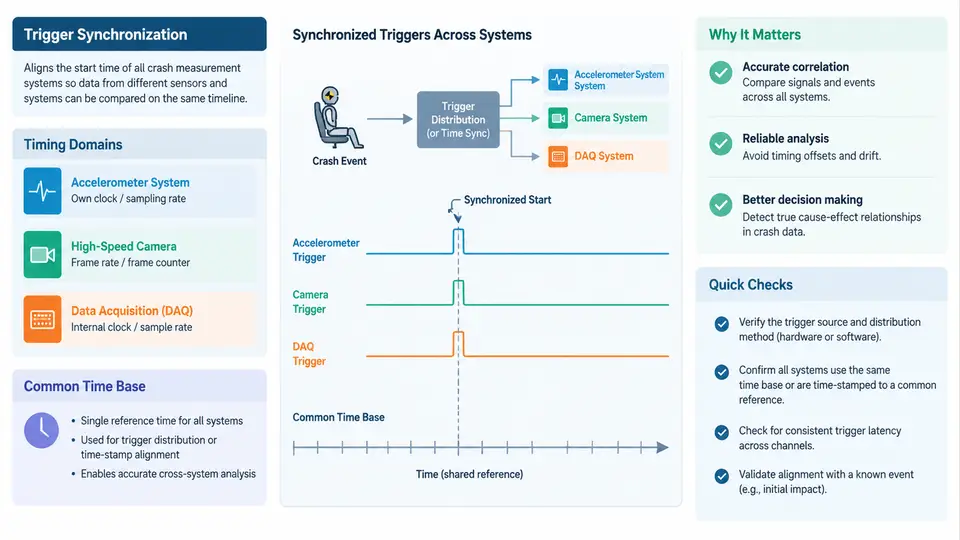
In a crash measurement system, the value of any single recorded channel depends on knowing when it was recorded relative to everything else. A seatbelt load of 4.2 kN means little on its own; it becomes engineering evidence only when you can state that it peaked 38 ms after bumper contact, while the airbag firing command occurred at 22 ms and the dummy head acceleration peaked at 71 ms. Trigger synchronization is the discipline that makes those relative statements trustworthy. This chapter establishes the vocabulary, the timing domains in which synchronization must be reasoned about, and the role of a common time base that ties all subsystems to one reference.
What "Trigger" and "Synchronization" Actually Mean
A trigger is any event, signal, or condition that causes a measurement system to commit data to memory in a defined way — typically starting or freezing a pre-trigger ring buffer, arming a recorder, or marking a reference point in a continuous stream. Triggers in crash testing come in several distinct flavors that are easy to conflate:
- Physical event triggers — a contact switch on the barrier face, a breakwire, or an accelerometer threshold crossing on the vehicle.
- Logical/arming triggers — a signal from the test controller that puts onboard recorders into an armed state before impact.
- Time-zero markers — an electrical pulse distributed to all recorders to define t = 0 for post-processing.
- Fire commands — outputs to pyrotechnic devices, which must be logged with the same time reference as the sensors they affect.
Synchronization is the process and the resulting property by which all of these events and all recorded channels share a known, bounded timing relationship. It is not a binary state. Synchronization quality is characterized by a residual offset (a constant or slowly varying difference between two clocks) and jitter (the sample-to-sample or event-to-event variation around that offset). A system can be well synchronized in offset but poorly synchronized in jitter, and the two failure modes have different consequences for analysis.
The Three Timing Domains
Synchronization problems are frequently misdiagnosed because engineers mix up three different domains. Keeping them separate is the single most useful habit in this subject.
| Domain | What it governs | Typical error source | Observable symptom |
|---|---|---|---|
| Event domain | When a trigger or marker physically occurs and is detected | Switch debounce, threshold hysteresis, cable delay | t = 0 appears shifted between subsystems |
| Sampling domain | When each ADC actually converts a sample | Independent sample clocks, clock drift, resampling | Channels drift apart over long records |
| Timestamp domain | What value the recorder attaches to each sample or event | Counter initialization, wrap-around, latency in stamping | Correct data with wrong labels |
Consider a concrete example. An onboard data logger samples at 20 kHz (50 µs period) using its own crystal, while an off-board high-speed camera runs at 1000 fps (1 ms frame period) locked to a different oscillator. Even if both are started by the same arming pulse, the logger's sample clock and the camera's frame clock are independent. Over a 200 ms crash event, a 50 ppm relative drift produces 200 ms × 50 × 10⁻⁶ = 10 µs of accumulated offset — negligible here, but the same 50 ppm over a 30 s sled run yields 1.5 ms, which is larger than a camera frame interval and will visibly misalign video against acceleration traces. The domain distinction tells you immediately that the fix is a shared time base, not a better trigger switch.
The Common Time Base
A common time base is a single reference — a clock, a pulse train, or a distributed timestamp protocol — from which all subsystems derive their notion of "now." In crash measurement practice it is implemented in one of three broad ways, and real facilities often combine them:
- Distributed reference pulse. A central controller emits a 1 PPS (pulse-per-second) or 10 Hz sync pulse over coax or fiber to every recorder. Each recorder counts pulses and interpolates with its local oscillator. Offset is bounded by pulse arrival skew (typically < 1 µs over short cable runs); drift between pulses is bounded by local oscillator stability.
- Shared clock signal. A 10 MHz reference (or an IRIG-B timecode carrying both time and a 1 kHz modulated carrier) is distributed continuously. IRIG-B is common in facilities that must correlate crash data with facility-wide timing, and it carries absolute time-of-day as well as a stable frequency reference.
- Protocol-based timestamping. Recorders on a network synchronize via IEEE 1588 PTP or GPS-disciplined clocks, stamping samples against a common epoch. This is increasingly used where onboard and off-board systems share an Ethernet backbone.
The choice matters because each method bounds a different quantity. A pulse-per-second scheme gives excellent short-term alignment but relies on oscillator holdover between pulses; a continuous clock reference gives better frequency stability but requires careful impedance matching and distribution amplification; PTP gives absolute time and scalability but introduces network-dependent asymmetry that must be characterized, not assumed.
Why the Common Time Base Is Not Optional
Three practical consequences follow from the architecture above. First, derived quantities inherit timing uncertainty. If you compute the delay between the fire command and peak airbag pressure, the uncertainty in that delay is the root-sum-square of the two channels' synchronization uncertainties, not just the sampling interval. A 1 ms offset between the fire-command logger and the pressure transducer can turn a genuine 3 ms deployment delay into a reported 2 ms or 4 ms — a difference that matters when comparing against a design target.
Second, pre-trigger data is only as good as the time base. Crash recorders typically hold 100–500 ms of pre-trigger ring buffer. If the arming trigger and the time-zero marker arrive on different references, the pre-trigger window is silently shifted, and any "before impact" baseline used for filtering or zeroing is contaminated.
Third, cross-system correlation requires a shared epoch, not just a shared start. Video, onboard logger, off-board DAQ, and fire-command logs are often processed by different teams on different software. Without a common epoch written into each file's header, alignment becomes a manual, error-prone exercise of matching visual features to acceleration onsets.
Establishing and Verifying the Time Base
In practice, a facility establishes its time base in a short pre-test procedure and verifies it with a measurable check rather than an assumption. A representative sequence for a sled test with an onboard logger, off-board DAQ, one high-speed camera, and a fire-command log:
- Distribute and terminate the reference. Connect the controller's 1 PPS and IRIG-B outputs to each subsystem with matched cable lengths where practical, and confirm 50 Ω termination at each input. Record the cable lengths; a 1 m mismatch in coax is roughly 5 ns of skew, usually negligible, but document it.
- Arm all recorders and confirm lock status. Each unit should report "reference locked" or an equivalent status bit. A unit that is armed but not locked will free-run and must be flagged.
- Inject a common marker. Fire a single electrical pulse into a spare channel on every recorder simultaneously. This is the verification artifact: it appears in every file and should land at the same timestamp (within the stated uncertainty) in each.
- Read back the marker timestamps. Compare the recorded marker time across files. The spread is your measured synchronization residual for this test configuration.
- Record the result in the test log alongside the configuration, so post-processing knows the uncertainty budget.
For the example configuration, a plausible (illustrative, not measured) result might be: onboard logger marker at 0.000 ms, off-board DAQ at +0.004 ms, camera frame-stamp at −0.6 ms (one frame boundary quantization), fire-command log at +0.002 ms. The camera's apparent offset is not a fault — it reflects frame quantization and must be handled as a known, bounded quantity during alignment rather than "corrected" by shifting the video arbitrarily.
Typical failure symptoms and their likely causes: a marker that appears in some files but not others points to a distribution or termination fault; a marker that drifts monotonically across a long record points to unlocked oscillators or a lost reference; a marker that is consistently offset by a fixed amount in one subsystem points to a timestamp-domain latency (for example, a recorder that stamps at buffer-write time rather than at conversion time). Each symptom maps to a different domain, which is why the domain vocabulary from earlier in this chapter is worth internalizing before touching hardware.
The takeaway for the rest of this course is straightforward: treat the common time base as a measured, documented, and bounded property of every test, not as a background assumption. Every subsequent topic — trigger distribution topologies, latency characterization, and post-test alignment — builds on the definitions and domain separation established here.