1. Preimpact sensing fundamentals
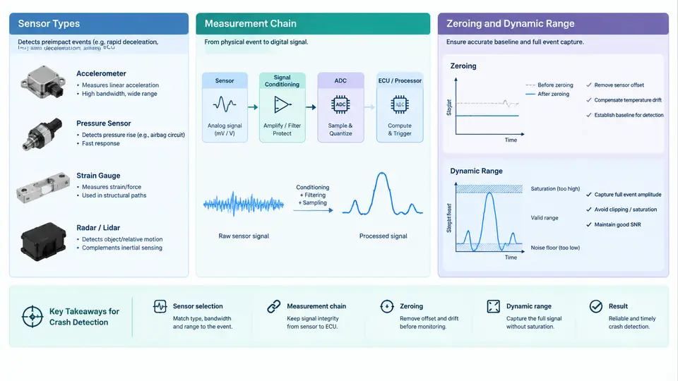
Preimpact sensing is the part of a crash-detection system that observes the vehicle and its occupants before the collision event fully develops. Its job is not merely to confirm that a crash happened, but to characterize the situation early enough that restraint decisions — airbag stage, seat-belt pretensioner force, battery disconnect, door unlock — can be made with the right timing and severity. Everything downstream depends on the quality of the raw signal, which is why zeroing and dynamic-range verification are treated as first-class calibration activities rather than routine maintenance.
Sensor types used in the preimpact window
Three families dominate the preimpact measurement problem, and each contributes a different physical quantity:
- Accelerometers (MEMS capacitive or piezoresistive). Typically mounted on the vehicle's longitudinal axis at the tunnel or sill, they measure deceleration in g. A ±50 g to ±250 g range is common for frontal sensing; the sensor's zero-g offset directly biases the integrated velocity estimate.
- Pressure sensors. Door-cavity or bumper pressure sensors detect the pressure pulse generated when a deformable structure is crushed. They respond faster than accelerometers to soft-body impacts and are used to discriminate pedestrian or low-mass collisions from rigid-barrier events.
- Radar, lidar, and camera (ADAS-grade). Forward-looking sensors provide range, relative velocity, and time-to-collision (TTC). Their output is not a crash signal per se, but a preimpact prediction that can pre-arm restraints or trigger reversible pretensioning.
Each sensor type has a distinct noise floor, bandwidth, and saturation behavior. A pressure sensor may saturate at a few hundred millibar during a hard crush, while an accelerometer saturates at its full-scale g limit. Knowing where each device saturates is the essence of dynamic-range management.
The measurement chain
The signal path from physical event to restraint decision is a chain, and every link can introduce offset, gain error, or clipping:
- Transduction. The MEMS element converts acceleration or pressure into a differential capacitance or resistance change.
- Analog front end (AFE). A charge amplifier or bridge amplifier converts the small signal to a voltage, typically with a gain of 20–100 V/g-equivalent.
- Anti-alias filtering and ADC. A low-pass filter (often 400–1000 Hz for crash channels) precedes a 10–16 bit ADC sampling at 1–10 kHz.
- Digital signal processing. Offset compensation, gain correction, and integration to velocity occur in the ECU firmware.
- Decision logic. Thresholds, energy integrals, and TTC estimates feed the restraint deployment algorithm.
Why zeroing matters
Zeroing establishes the sensor's output at the true zero-input condition. For an accelerometer, that means the output voltage when the vehicle is level and stationary (or, for a 1-axis sensor, when gravity is orthogonal to the sensing axis). The zero-g offset arises from MEMS manufacturing tolerances, package stress, and temperature drift. If it is not removed, the integrated velocity starts from a non-zero baseline and the crash algorithm sees a phantom Δv before the impact even begins.
In practice, zeroing is performed in two stages. First, a factory or end-of-line (EOL) calibration writes a coarse offset into non-volatile memory using a precision tilt table or a known reference. Second, a runtime auto-zero continuously updates the offset while the vehicle is stationary and the ignition is on, using a long time constant (typically 10–60 s) so that real accelerations are not mistaken for drift. The runtime update must be inhibited whenever the vehicle is moving, because a sustained acceleration (e.g., a long uphill grade) would otherwise be learned as offset.
Why dynamic range matters
Dynamic range is the ratio between the smallest resolvable signal and the largest signal before saturation. For crash sensing, the relevant span is roughly 0.01 g (the noise floor that determines whether a gentle bumper tap is detectable) up to the full-scale limit (the hardest barrier impact the sensor must survive without clipping). A sensor with ±50 g full scale and 0.01 g resolution offers about 74 dB of dynamic range — adequate for frontal sensing but marginal for high-severity events.
Two failure modes are worth distinguishing. Under-ranging causes clipping: the accelerometer output flat-tops at full scale, the integrated velocity underestimates Δv, and the algorithm may under-deploy. Over-ranging (choosing a very high full-scale sensor) raises the noise floor and reduces resolution for low-severity events, making pedestrian detection and low-speed discrimination unreliable. The correct choice is driven by the crash modes the vehicle must handle, not by a single worst-case number.
Putting it together: a worked example
Consider a frontal accelerometer specified at ±50 g full scale, 0.01 g resolution, and a 0.05 g maximum zero-g offset. During EOL calibration on a level surface, the measured output is 2.512 V against a nominal 2.500 V zero point, implying a +0.048 g offset. The calibration writes −0.048 g into the offset register. At runtime, the auto-zero routine confirms the residual is within ±0.02 g before enabling the crash algorithm.
Now suppose a 30 km/h rigid-barrier impact produces a peak deceleration of 42 g. The sensor remains within its ±50 g range, so the signal is not clipped and the integrated Δv is trustworthy. If the same vehicle were fitted with a ±25 g sensor, the peak would clip at 25 g, the integrated Δv would be underestimated by roughly 30–40%, and the algorithm might select a lower airbag stage than required. Conversely, a ±200 g sensor would raise the noise floor to about 0.04 g, degrading low-speed pedestrian discrimination. The dynamic-range check is therefore a trade study, not a single pass/fail test.
Verification criteria
A preimpact sensing channel is considered ready when three conditions hold: the residual zero-g offset is within the specified tolerance (e.g., ±0.02 g) after runtime auto-zero; the full-scale clipping margin is at least 20% above the highest expected crash pulse for the vehicle's target modes; and the noise floor is low enough that the smallest event of interest (e.g., a 5 km/h bumper contact) produces a signal-to-noise ratio of at least 6 dB. These three numbers — offset, clipping margin, and SNR — are the practical summary of everything the measurement chain must deliver before the decision logic can be trusted.