1. Introduction to Hybrid III ATD
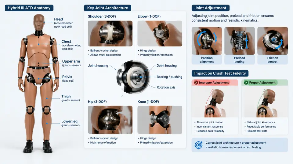
The Hybrid III Anthropomorphic Test Device (ATD) is the reference occupant surrogate for frontal-impact crash testing under FMVSS 208, ECE R94, and most consumer-rating protocols such as Euro NCAP and C-NCAP. Unlike a crash dummy in the colloquial sense, the Hybrid III is a calibrated measuring instrument: every limb segment, spinal element, and joint is designed so that its mass distribution, stiffness, and kinematics approximate those of a 50th-percentile adult male. When a test report states that the driver's chest deflection was 42 mm or that the left femur recorded 6.8 kN, those numbers are only meaningful if the ATD was assembled and adjusted to its certified configuration. Joint adjustment is the bridge between a box of components and a legally defensible measurement device.
Anatomical Layout of the 50th-Percentile Male
The device is organized into five functional regions, each with its own instrumentation and adjustment points:
- Head and neck. An aluminium skull with a vinyl skin, a six-axis upper-neck load cell, and a three-axis lower-neck load cell. The neck is a segmented butyl-rubber column with steel discs; its stiffness is fixed at manufacture, but its mounting orientation and preload are set during assembly.
- Thorax. A steel rib cage with six rib modules, a sternum, and a spine box containing the thoracic and lumbar load cells. Chest deflection is measured by a potentiometer or string potentiometer mounted on the sternum.
- Lumbar spine and pelvis. A curved lumbar spine element that provides realistic flexion, and an aluminium pelvis with iliac wings that locate the lap belt.
- Upper extremities. Shoulder, elbow, and wrist joints with adjustable friction, terminated by a vinyl hand.
- Lower extremities. Hip, knee, and ankle joints, femur and tibia load cells, and a foot with an adjustable ankle angle.
Each region carries a serial-numbered certificate listing its calibration date and measured response values. Mixing components from different ATDs is permitted only within the manufacturer's documented tolerance, and the resulting assembly must be re-verified.
Joint Architecture: What Each Joint Must Do
The Hybrid III uses two fundamentally different joint philosophies, and confusing them is a common source of setup error.
Friction joints (shoulder, elbow, wrist, hip, knee, ankle) are ball-and-socket or clevis assemblies whose resistance is set by a torque on a clamping screw or by a Belleville-spring stack. The specification is expressed as a breakaway torque or a force measured at a defined lever arm. For example, the knee joint is typically set so that the leg extends under a specified applied moment, and the shoulder is set so the arm holds position against gravity but yields under belt loading. These joints are adjusted, not calibrated, and they drift with use.
Instrumented or fixed joints (neck-to-head, neck-to-thorax, lumbar-to-pelvis) are not user-adjustable in stiffness. Their critical setup parameters are orientation and fastener torque: the neck must be mounted at the specified angle, and the mounting bolts must be tightened to the published value with a calibrated torque wrench. Over-torquing crushes the rubber column and biases neck-moment readings; under-torquing allows relative motion that corrupts the same channels.
Why Joint Adjustment Determines Test Fidelity
Crash-test fidelity depends on the ATD reproducing the same initial state in every run. Consider three concrete mechanisms:
- Pre-impact posture. If the shoulder friction is too low, the arm drops before impact and the dummy's hand may contact the door or airbag differently, changing chest loading. If the hip friction is too low, the pelvis rotates and the lap belt migrates onto the abdomen, inflating abdominal injury metrics.
- Load-path integrity. A neck mounting bolt at 60% of specified torque allows micro-slip during the crash pulse, adding high-frequency content to the upper-neck moment and potentially triggering a false injury criterion exceedance.
- Repeatability across the fleet. Laboratories that run the same sled test weekly rely on joint settings staying within tolerance. A drift of a few degrees in ankle angle changes footwell intrusion interaction and hence tibia index values.
The practical consequence is that joint adjustment is a documented, measured, and recorded activity, not a "snug it up" step. Every setting should be traceable to a torque value or a measured breakaway force, recorded on the ATD setup sheet, and re-checked at the interval specified by the manufacturer or the test protocol.
From Anatomy to Adjustment Practice
Because the ATD is a system of joints, the setup workflow is best organized around them rather than around body regions. A practical sequence used in many labs is: verify the certificate and serial numbers, mount the head and neck with a calibrated torque wrench, set the lumbar and pelvis, then work outward through the limbs, finishing with the extremities. At each friction joint, apply the specified breakaway torque with a torque screwdriver or a spring gauge at the defined lever arm, and record the measured value. A representative setup record for a single ATD might look like this (values are illustrative and must be replaced by the values in the applicable manual and protocol):
ATD S/N: H3-50M-0417        Date: 2025-03-11
Technician: R. Okafor        Protocol: FMVSS 208 frontal, 56 km/h

Joint / fastener          Spec (example)        Measured        Status
------------------------- --------------------- --------------- ------
Neck-to-head bolts        47 N·m                47.2 N·m        PASS
Neck-to-thorax bolts      47 N·m                46.8 N·m        PASS
Shoulder breakaway        1.4–2.3 N·m @ 0.15 m 1.9 N·m         PASS
Elbow breakaway           1.0–1.7 N·m @ 0.10 m 1.3 N·m         PASS
Hip breakaway             2.0–3.4 N·m @ 0.20 m 2.7 N·m         PASS
Knee breakaway            1.5–2.5 N·m @ 0.15 m 2.1 N·m         PASS
Ankle angle               90° ± 2°              90.5°           PASS
Two observations matter here. First, the measured values sit inside the band but are not identical to the nominal — that is expected, and the record is what makes the run traceable. Second, the ankle angle is recorded in degrees, not torque, because the ankle is set by a positive stop rather than by friction. Recognizing which quantity applies to which joint is part of the competence this course builds.
What "Adjusted" Actually Means in a Test Report
When a test house signs off a frontal test, the ATD setup sheet becomes part of the test documentation. If a regulator or a counterpart lab later questions a chest deflection value, the first thing they will ask for is the joint adjustment record and the calibration certificates. A joint that was "about right" is not defensible; a joint that was measured, recorded, and within the published band is. This is why the remainder of this course treats joint adjustment as a measurement discipline rather than a mechanical chore — the ATD's anatomy defines where the joints are, but the adjustment record defines whether the numbers produced by that anatomy can be trusted.