1. Crash test sensor systems overview
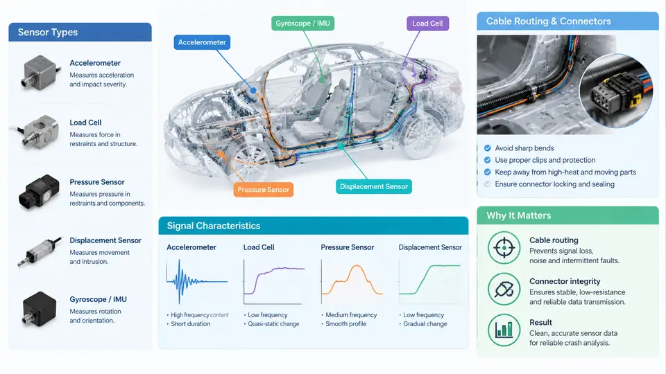
A crash test is only as trustworthy as the measurement chain that feeds it. Before any occupant injury criterion, structural deformation value, or airbag deployment timing can be reported, dozens of transducers must convert physical events into electrical signals that survive the hostile environment of a barrier impact. This chapter establishes the system-level view: which sensor families are used, what their signals look like, and why cable routing and connector integrity are treated as first-class engineering concerns rather than installation housekeeping.
Sensor families and their signal characteristics
Crash test instrumentation generally falls into four functional groups, each with distinct electrical behavior that constrains how the cable must be handled.
- Accelerometers (piezoresistive and capacitive). Typically single-axis or triaxial, mounted on the vehicle structure, seat frames, or dummy segments. Output is an analog voltage proportional to acceleration, often ±50 g to ±2000 g full scale, with bandwidth from DC to several kHz. Because the signal is small and referenced to a supply, any added series resistance or ground shift from a poor connector appears directly as measurement error.
- Load cells and force transducers. Used in barriers, seat belts, steering columns, and dummy femurs. Output is a low-level bridge signal (millivolt range), frequently conditioned by an in-line amplifier. Bridge circuits are sensitive to lead resistance, so contact resistance in a connector becomes a gain error, not just noise.
- Potentiometers and string potentiometers. Measure displacement such as pedal travel, steering wheel intrusion, or dummy chest deflection. Output is a ratiometric voltage; the wiper contact is mechanically fragile and the cable must not impose side load on the sensor body.
- Pressure and temperature sensors. Used for tire pressure, fuel tank, and dummy internal cavities. Slower signals, but often routed near high-current pyrotechnic lines, making them susceptible to coupled noise.
Two signal classes dominate the electrical design. High-level signals (conditioned ±5 V or ±10 V) tolerate moderate cable loss but still require a clean, low-impedance ground reference. Low-level bridge and thermocouple signals operate in the millivolt domain and demand shielded, twisted pairs with a single-point shield ground. Mixing these classes on a shared harness without separation is one of the most common causes of corrupted crash data.
Why routing and connector integrity determine data quality
During a 50 km/h frontal impact, the vehicle decelerates from roughly 14 m/s to rest in about 100 ms, producing peak accelerations well above 30 g at the structure and severe relative motion between body, dummy, and restraint systems. Cables experience tension, flexure, abrasion against sharp sheet metal, and electromagnetic fields from airbag firing circuits. Three failure mechanisms follow directly:
- Intermittent contact. A partially seated connector or a crimp with marginal pull-out force can open for a few milliseconds at peak g. The result is a dropout that looks like a real signal transient and may be misread as sensor saturation or a structural event.
- Ground offset and shield noise. Long unshielded runs near firing lines couple current into the signal return. Because accelerometers are referenced to their supply ground, a few hundred millivolts of ground shift translates into tens of g of apparent acceleration.
- Mechanical strain and abrasion. Cables routed without service loops are loaded in tension as the structure deforms; insulation chafes through and creates a short to chassis, usually at the worst possible moment.
Signal chain from transducer to data acquisition
The figure below traces a representative channel from transducer to recorder, showing where routing and connector decisions enter the measurement loop and what each stage contributes to the final data quality.
Practical example: qualifying a single accelerometer channel
Consider a uniaxial ±500 g accelerometer mounted on the B-pillar, feeding a channel sampled at 20 kHz. The following sequence is representative of a pre-test integrity check; the values are illustrative teaching targets, not measured results.
1. Visual: connector fully seated, lock tab engaged, no tension on pigtail.
2. Contact resistance: measure across mated pair, expect < 10 mΩ per contact.
3. Pull test: apply 30 N axial pull for 5 s; no movement, no continuity break.
4. Shield check: shield-to-chassis > 1 MΩ at sensor end; shield bonded at DAQ end.
5. Tap test: tap sensor body lightly; observe a clean, decaying pulse with no
   step change or baseline shift on the live channel.
6. Baseline: record 2 s of static data; verify offset within ±0.5 g and noise
   floor consistent with the sensor datasheet.
If step 5 shows a step change rather than a decaying pulse, suspect a marginal crimp or a partially seated pin. If step 6 shows elevated noise or a drifting offset, inspect the shield termination and the proximity of the run to airbag firing lines. These symptoms are diagnostic: they distinguish a mechanical contact problem from an electromagnetic coupling problem, which require different corrective actions.
Design rules that follow from the signal chain
Three rules recur across every crash test program and should be treated as defaults until a specific measurement justifies an exception. First, separate signal classes: route millivolt bridge and thermocouple lines in their own shielded bundles, physically distant from firing circuits and high-current grounds. Second, provide strain relief and service loops at every sensor and at every bulkhead crossing, so that structural deformation loads the loop rather than the connector. Third, ground shields at one end only, normally the data acquisition end, to avoid ground loops that inject current into the signal return.
Connector integrity deserves its own discipline. Use connectors rated for the vibration and temperature profile of the test, verify mating force and lock engagement by hand and by pull test, and record contact resistance for critical channels before and after the test. A connector that passes continuity but fails a 30 N pull test is a latent failure waiting for peak g.
What good data quality looks like
At the system level, a well-instrumented crash test channel exhibits four properties: a stable pre-trigger baseline with offset inside the sensor's specified tolerance; a noise floor consistent with the datasheet and the chosen filter; no step discontinuities or dropouts during the impact window; and a post-event return to a physically plausible rest state. When any of these is violated, the first diagnostic step is to trace back along the chain shown above — connector, cable route, shield termination, conditioning — rather than to adjust the data in post-processing. The measurement chain is only as strong as its weakest contact, and in crash testing the weakest contact is almost always the one that was never pull-tested.