1. Crash test instrumentation overview
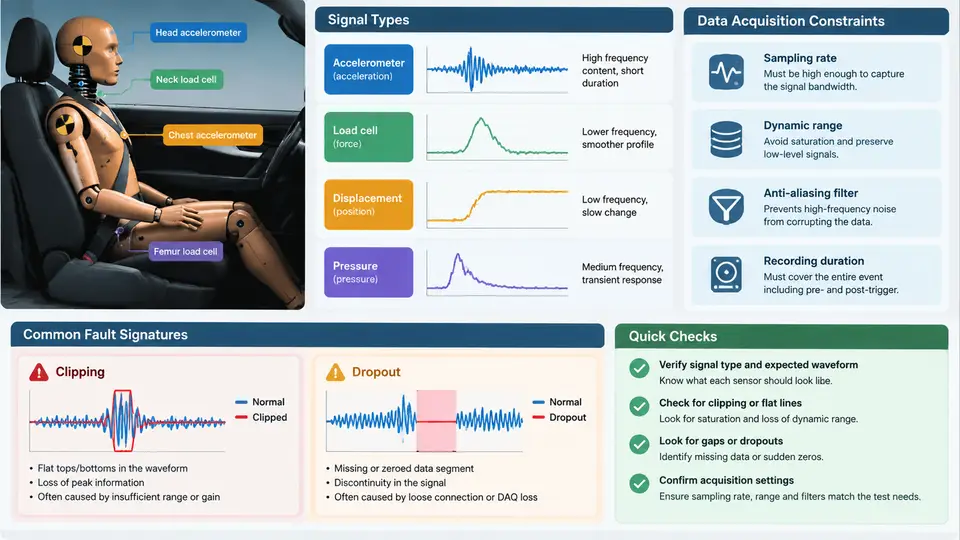
Clipping and dropout faults are not random events that appear out of nowhere during a crash test. They are the predictable consequence of how a measurement chain is designed, where sensors are mounted, and how the data acquisition system is configured. Before we can isolate a clipped accelerometer channel or a dropped strain gauge reading, we need a clear picture of the instrumentation architecture that produces those signals in the first place. This chapter establishes that baseline: what kinds of signals a crash test generates, where the sensors sit on the vehicle and the dummy, and which data acquisition constraints create the conditions under which clipping and dropout become likely.
Signal Types in a Crash Test
A full-scale frontal or side impact test typically carries 80 to 200 active channels. They fall into a small number of physical categories, and each category has its own failure signature when the measurement chain is stressed.
- Accelerometers — the dominant channel type. They measure vehicle structure acceleration (B-pillar, sill, tunnel, engine cradle), dummy head/chest/pelvis acceleration, and seat or restraint anchor acceleration. Typical ranges are ±500 g for vehicle structure and ±2000 g for head impact locations. These are the channels most exposed to clipping because crash pulses contain high-frequency content that can momentarily exceed the nominal full-scale range.
- Load cells and force transducers — seat belt load cells, steering column force, pedal force, and dummy femur/neck load cells. Ranges commonly span 5 kN to 20 kN. They are prone to dropout when connector retention fails under vibration.
- Strain gauges — applied to structural members, door frames, and restraint anchors. Low-level millivolt outputs make them sensitive to ground offsets and lead-wire faults.
- Displacement and rotation sensors — string potentiometers, rotary potentiometers, and optical ride-height sensors used to track steering wheel intrusion, pedal travel, and dummy kinematics.
- Pressure and temperature — tire pressure, airbag inflator pressure, and dummy chest-band pressure where applicable.
- Discrete and event channels — airbag firing current, seatbelt pretensioner trigger, and the test-event zero-time pulse that anchors all other channels in time.
The distinction matters because clipping is fundamentally an amplitude-range problem, while dropout is fundamentally a continuity and timing problem. Accelerometers and load cells dominate the clipping risk; strain gauges and any channel routed through a multi-pin bulkhead connector dominate the dropout risk.
Sensor Placement and Its Effect on Fault Exposure
Placement determines both the mechanical environment a sensor sees and the cable path it must survive. Three placement zones behave very differently.
Vehicle structure sensors are mounted on rigid members close to the impact path — the non-impacted B-pillar, the rocker sill, the tunnel, and the rear seat cross-member. These locations experience the full crash pulse with sharp onset. A sill-mounted accelerometer may see a 40 g to 80 g peak within 10 ms, with superimposed structural ringing that pushes instantaneous values well above the nominal peak. This is the classic clipping scenario: the channel is correctly ranged for the bulk pulse but under-ranged for the high-frequency transient.
Dummy-mounted sensors sit inside the ATD (anthropomorphic test device) and are routed through the dummy's internal cabling to a umbilical that exits at the pelvis or lower back. Head accelerometers are triaxial packages at the head CG; chest accelerometers sit on the sternum and spine; pelvis accelerometers are at the iliac crest. The umbilical is a known dropout point because it flexes and can be pinched during dummy positioning.
Restraint and interior sensors — belt load cells, buckle switches, steering column force — are mounted on components that move relative to the body during the crash. Their lead wires must accommodate that relative motion, and a wire that is routed too tight will either pull free (dropout) or chafe against structure (intermittent dropout followed by open circuit).
Data Acquisition Constraints That Create Faults
The DAQ system is where clipping and dropout are either prevented or baked in. Four constraints dominate.
Full-scale range and resolution. Most crash DAQ systems digitize at 16-bit resolution over a selectable input range. A ±500 g range with 16 bits gives roughly 0.015 g per count — excellent resolution, but the range ceiling is a hard limit. If the true signal reaches 620 g, the channel saturates and the recorded waveform flat-tops. The engineer must choose between range headroom and resolution, and that trade-off is the root cause of most clipping faults.
Anti-alias filtering and sample rate. Crash data is typically sampled at 10 kHz to 20 kHz per channel with a low-pass anti-alias filter set near 3 kHz to 5 kHz (SAE J211 recommends channel filter class depending on the measurement). A filter that is set too low will round off the very transient that would have revealed a clip; a filter set too high admits content that can drive the input stage into saturation between samples.
Channel count and multiplexing. High channel counts force multiplexed front-ends on some systems, which introduces settling time between samples. A channel with a slow-settling input stage can show a false dropout-like step when the preceding channel carries a large signal.
Power, grounding, and cable shielding. The vehicle under test is a noisy electrical environment — airbag firing circuits, pyrotechnic triggers, and the tow system all inject transients. A ground offset between the sensor return and the DAQ reference appears as a DC shift; a broken shield appears as high-frequency noise that can mask a dropout. Battery-backed DAQ systems must hold their supply through the crash event; a momentary supply dip will reset the front-end and produce a gap in every channel simultaneously — a system-level dropout that is easy to misdiagnose as a sensor fault.
Why the Instrumentation Baseline Matters for Fault Isolation
The practical payoff of this overview is diagnostic discipline. When a channel shows a flat top at exactly the configured full-scale value, the fault is almost certainly clipping, and the fix is a range change or a re-test with a higher-range sensor — not a cable inspection. When a channel steps abruptly to zero mid-pulse while its neighbors continue normally, the fault is continuity in that channel's path, and the inspection should start at the connector nearest the relative-motion interface. When every channel gaps at the same sample, the fault is system-level — supply, time-zero, or the DAQ front-end — and no amount of sensor swapping will help.
Two pre-test practices make these distinctions reliable. First, record the configured full-scale range and filter class for every channel in the setup log, so a post-test flat top can be compared against the known rail rather than guessed at. Second, run a continuity and shield-integrity check on every channel after final dummy positioning and before the tow, because the positioning process is when umbilical and restraint leads are most likely to be disturbed. A channel that fails continuity at that stage is a dropout waiting to happen, and catching it before the crash is far cheaper than explaining a gap in the post-test data review.
With this baseline in place — signal categories, placement zones, cable paths, and DAQ constraints — the next step is to characterize what a clipped or dropped channel actually looks like in the recorded data, and to build the isolation logic that moves from symptom to root cause without guesswork.