1. Introduction to barrier positioning and
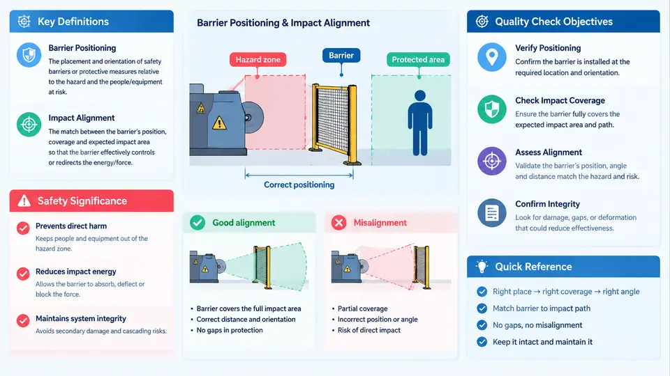
In roadside safety engineering, a barrier is only as effective as its position relative to the hazard it protects and the traffic it must redirect. Barrier positioning is the process of establishing the barrier's lateral offset from the traveled way, its longitudinal limits (length of need), its height above the pavement or ground line, and its transition and terminal locations. Impact alignment is the geometric and structural compatibility between the approaching vehicle trajectory and the barrier face — the angle at which a vehicle is expected to strike, the barrier's face orientation, the flare rate of transitions, and the continuity of the load path from the rail or cable into posts, anchors, and the ground.
These two concepts are inseparable. A barrier placed at the correct offset but aligned so that its terminal presents a blunt end to oncoming traffic converts a protective device into a hazard. Conversely, a perfectly aligned W-beam run positioned too close to the edge of the traveled way reduces the recovery distance available to an errant vehicle and increases the frequency and severity of impacts. Quality checks exist to verify that both conditions — position and alignment — are satisfied before the installation is accepted and throughout its service life.
Why Position and Alignment Govern Safety Performance
Crash-tested barrier systems are qualified under standardized impact conditions: a specified vehicle mass, speed, and approach angle striking the barrier at a defined lateral offset and height. The NCHRP Report 350 and the later AASHTO Manual for Assessing Safety Hardware (MASH) define these conditions. A W-beam guardrail, for example, is typically evaluated with a 1,100 kg passenger car and a 2,270 kg pickup truck at 100 km/h and a 25-degree approach angle. The system's capacity to contain and redirect the vehicle depends on the rail being at the tested height (typically 550–700 mm to the top of rail for W-beam), the posts being at the tested spacing and embedment, and the face being oriented so the vehicle engages the rail rather than passing beneath or over it.
When field position deviates from the tested configuration, performance degrades in predictable ways:
- Excessive lateral offset from the edge of the traveled way increases the likelihood that a vehicle leaves the roadway before reaching the barrier, and it enlarges the unsupported span where the vehicle can drop off the shoulder.
- Insufficient offset places the barrier within the clear zone recovery area, so the barrier itself becomes the first object struck rather than a last resort.
- Low rail height allows the vehicle to ride over the rail (vaulting) or submarine beneath it; high rail height lets the vehicle pass under the rail and strike the posts directly.
- Misaligned transitions and flares produce concentrated loading at the flare, causing rail rupture or post pull-out instead of smooth redirection.
- Terminal misalignment — a turned-down or turned-up terminal facing traffic, or a terminal not flared away from the traveled way — creates a spearing or ramping hazard.
The Quality Check Objectives
Positioning and alignment quality checks serve four distinct objectives, and each maps to a different verification method:
- Conformance to the tested design. Confirm that offset, height, post spacing, embedment depth, rail type, and terminal type match the approved standard or site-specific design. This is a documentation-and-measurement check: compare as-built values against the design drawings and the manufacturer's installation manual.
- Geometric continuity. Verify that the barrier line is smooth, that transitions between different barrier types or stiffnesses are flared at the specified rate, and that there are no unintended kinks, sags, or abrupt changes in face orientation. This is a survey check using string lines, offset measurements at regular stations, and profile leveling.
- Load-path integrity. Confirm that posts are driven or embedded to the required depth, that blockouts and backup plates are present and correctly oriented, that splices are located and bolted as specified, and that anchorages at bridge decks and culverts are engaged. This is a physical inspection with torque checks and embedment verification.
- Hazard clearance and sight distance. Ensure the barrier does not intrude into the clear zone in a way that creates a new fixed-object hazard, does not obstruct required sight distance at intersections or ramps, and maintains the specified shy distance from curbs, drainage structures, and utilities.
The following diagram shows how the key positioning and alignment parameters relate to one another along a typical guardrail installation, from the traveled way edge through the transition to the terminal.
From Definition to Field Verification
Consider a representative field scenario to see how these objectives translate into practice. A two-lane rural highway with a 100 km/h posted speed has a culvert headwall on the outside of a horizontal curve. The design calls for a W-beam guardrail with a 2,000 mm post spacing, a 700 mm rail height, and a flared terminal. The clear zone width for this speed and traffic volume is 7.0 m from the edge of the traveled way.
The quality check proceeds in a defined sequence. First, the survey crew establishes the edge of the traveled way as the reference datum and measures the lateral offset to the barrier face at 10 m stations. The design offset is 2.5 m; any station reading outside ±75 mm of that value is flagged. Second, a string line is stretched along the barrier face between the terminal and the first transition to check for plan-view deviation — a sag or kink greater than 25 mm over a 3 m span indicates a post that has shifted or a rail that is not properly lapped. Third, rail height is measured with a level and staff at each post; readings below 650 mm or above 750 mm are recorded for correction. Fourth, embedment is verified by probing or by checking the post driving records against the specified depth, and splice bolts are torque-checked to the manufacturer's value.
The expected output of this check is a station-by-station record of offset, height, and deviation, with each value compared against its tolerance. A station that reads 2.65 m offset, 640 mm rail height, and a 30 mm plan deviation is not a single defect — it is a cluster that suggests the post at that station was driven off-line and possibly shallow, which would explain both the low rail and the kink. The troubleshooting response is to pull and redrive that post rather than to shim the rail, because shimming corrects the visible height without restoring the load path.
What the Check Is Really Protecting Against
The ultimate purpose of positioning and alignment checks is not documentation compliance for its own sake. Each tolerance corresponds to a failure mode observed in crash testing or field performance. Offset tolerance protects the recovery distance and the barrier's ability to engage the vehicle at the tested angle. Height tolerance protects against vaulting and underride. Plan-view continuity protects against concentrated loading and rail rupture. Embedment and splice checks protect the anchorage that resists the overturning moment applied by an impact. When a check is skipped, the barrier may still look correct and may still perform adequately for small impacts, but its margin against the design impact — the one condition it was selected to survive — is unknown and possibly absent.
With these definitions and objectives established, subsequent work can move into the specific measurement methods, tolerance values, and documentation formats that make each check repeatable and auditable.