1. Crash signal measurement chain
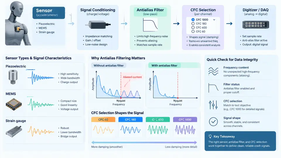
Every crash test produces a measurement chain that begins at a physical transducer and ends as a sampled digital record. Between those two points, the signal passes through cabling, signal conditioning, analog anti-alias filtering, sampling, and digital channel filtering. Each stage shapes what the final record can legitimately represent. Understanding this chain is the prerequisite for choosing a CFC (Channel Frequency Class) and for judging whether a reported peak, pulse duration, or slope is a property of the crash event or an artifact of the processing.
Sensor types and what they actually measure
Crash testing relies on a small family of transducer types, each with distinct bandwidth and failure modes:
- Piezoresistive accelerometers — the workhorse for vehicle structure and sled measurements. They are DC-capable (static acceleration, e.g., gravity offset, is measurable), have ranges typically from ±50 g to ±2000 g, and damped resonant frequencies in the tens of kHz. Their DC response makes them suitable for inertial and low-frequency content, but it also means offset drift and gravity orientation must be handled.
- Piezoelectric (charge-mode) accelerometers — high sensitivity and wide dynamic range, but AC-coupled in practice; they cannot report static acceleration. Used where high-frequency content matters, such as component-level impact.
- Load cells and force transducers — strain-gauge based, used for belt force, seat force, and barrier load measurement. Bandwidth is lower than accelerometers, and mechanical mounting stiffness dominates the usable range.
- Potentiometric and string potentiometers, rotary encoders — displacement and rotation, e.g., steering wheel movement, pedal travel, dummy chest deflection via IR-TRACC or similar devices.
- Anthropomorphic test device (ATD) internal sensors — accelerometers, load cells, and deflection sensors inside the dummy, each with its own specified channel class in the applicable regulation or consumer protocol.
The critical point is that a sensor's specified frequency range is a claim about its usable passband, not a guarantee that everything above it is absent. Mechanical resonance, cable microphonics, and amplifier noise all contribute out-of-band energy that must be removed before sampling.
Signal characteristics of a crash pulse
A typical vehicle body acceleration pulse during a frontal rigid-barrier impact lasts roughly 80–150 ms, with a peak in the 30–60 g range for a passenger car at 50–64 km/h. The energy is concentrated below a few hundred hertz, but the waveform is far from band-limited: the initial impact generates a sharp rise with significant high-frequency content, and structure-borne ringing appears as superimposed oscillation. Dummy channels such as head acceleration can contain higher-frequency components, and chest deflection or belt force channels are comparatively slow.
This spectral spread is exactly why a single fixed filter setting cannot serve all channels. A filter wide enough to preserve the sharp head acceleration onset will pass structural ringing on a vehicle rail channel; a filter narrow enough to smooth the rail channel will attenuate the head peak and shift its timing.
Why anti-alias filtering is non-negotiable
Sampling converts a continuous signal into discrete values at interval Δt, corresponding to a sampling rate fs = 1/Δt. The Nyquist frequency is fs/2. Any spectral content above fs/2 is folded back into the baseband and becomes indistinguishable from genuine low-frequency content. In crash data this is not a theoretical concern: a 20 kHz sampling rate gives a 10 kHz Nyquist limit, and an accelerometer with a 30–50 kHz mounted resonance will happily deliver energy above that limit, which then aliases into the recorded pulse.
The defense is an analog low-pass filter placed before the sampler, with a stopband that reaches adequate attenuation by fs/2. In practice, data acquisition systems for crash testing use steep analog anti-alias filters (often 8th-order or higher) with a corner frequency well below Nyquist, and they oversample relative to the final channel class. A common architecture is: analog anti-alias filter → sample at a high rate → digital decimation/filtering to the specified CFC class. The analog stage protects against aliasing; the digital stage defines the reported bandwidth.
CFC selection: defining the reported bandwidth
CFC classes are standardized low-pass filter specifications (SAE J211/1 and ISO 6487 are the reference documents) that define a Butterworth-type magnitude response by a corner frequency fc and a tolerance band. The commonly used classes are CFC 60, CFC 180, CFC 600, and CFC 1000, with corner frequencies of 60, 180, 600, and 1000 Hz respectively. The class number equals the corner frequency in hertz.
| CFC class | Corner frequency fc | Typical application | Minimum practical sample rate |
|---|---|---|---|
| CFC 60 | 60 Hz | Vehicle structure, belt force, chest deflection, slower ATD channels | ≥ 600 Hz (10× fc) |
| CFC 180 | 180 Hz | General ATD accelerations, many body channels | ≥ 1800 Hz |
| CFC 600 | 600 Hz | Head acceleration, stiff component impact | ≥ 6000 Hz |
| CFC 1000 | 1000 Hz | High-bandwidth component and special studies | ≥ 10000 Hz |
The sample-rate column reflects the practical rule that the acquisition rate should be at least ten times the CFC corner frequency, so that the digital filter's transition band and the analog anti-alias stage both have room to work. Many labs acquire all channels at a common high rate (e.g., 20 kHz or 100 kHz) and apply the channel-specific CFC digitally, which keeps timing aligned across channels.
CFC selection is not a free engineering choice in regulated testing. Frontal impact dummy channels, for example, are assigned specific classes by the regulation or consumer protocol, and reporting a head acceleration at CFC 180 instead of CFC 600 would understate the peak and misrepresent the injury metric. Where the protocol is silent, the selection principle is: choose the lowest class that still preserves the physically meaningful content of that channel, and document the choice.
How the chain shapes the reported result
Consider a head accelerometer channel acquired at 20 kHz with an analog anti-alias corner near 4 kHz, then digitally filtered to CFC 600. The analog stage removes content above roughly 10 kHz that would otherwise alias; the CFC 600 stage attenuates content above 600 Hz with the standardized roll-off. The reported peak occurs slightly later and is slightly lower than the unfiltered peak, and the HIC calculation uses the filtered waveform. If the same raw data were filtered to CFC 180, the peak would drop further and the pulse would broaden — a different, and for this channel incorrect, result.
The practical verification is straightforward: confirm the acquisition sample rate, confirm the analog anti-alias corner and order from the DAQ specification, confirm the digital CFC applied in post-processing, and check that the reported channel class matches the protocol. A quick sanity check is to compare the unfiltered and CFC-filtered peaks; a large discrepancy on a channel expected to be smooth suggests either an inappropriately wide class or contamination that the anti-alias stage should have removed.
Practical implications for channel setup
Three habits keep the chain defensible. First, record the acquisition configuration alongside the data: sample rate, analog anti-alias corner and order, and the digital CFC applied. Second, verify that the analog anti-alias corner is comfortably below Nyquist — a corner at 4 kHz with 20 kHz sampling leaves a full octave of transition band before the 10 kHz limit, which is a reasonable margin for an 8th-order filter. Third, apply the CFC class mandated by the protocol for each channel and do not substitute a class because the waveform "looks cleaner."
When a result looks suspicious — an implausibly sharp peak, a step discontinuity, or a channel whose filtered and unfiltered peaks differ by more than expected — the first diagnostic is to inspect the raw, pre-CFC data for high-frequency contamination and to confirm the analog filter settings. Aliasing artifacts often appear as low-frequency beating or as a spurious slow oscillation that does not correspond to any physical event. Recognizing them requires knowing the chain, which is why the measurement architecture deserves attention before any single number is reported.