1. Accelerometer axis orientation fundament
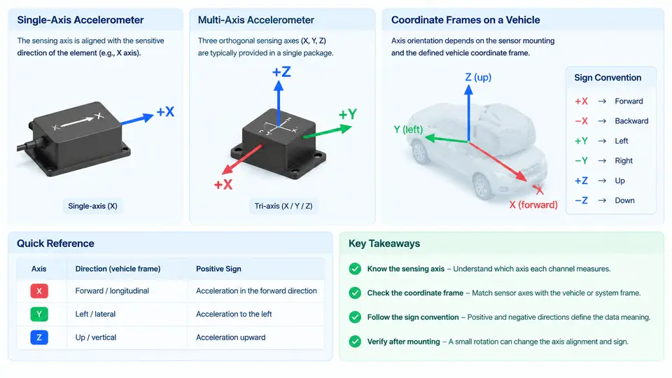
Every accelerometer measurement is a vector quantity, and a vector is meaningless without a frame in which it is expressed. Before any discussion of mounting error, misalignment, or cross-axis sensitivity becomes useful, the engineer must be able to answer three questions precisely: along which physical direction does each sensing axis point, in which coordinate frame is the output expressed, and which polarity convention maps a positive acceleration to a positive number. Getting these three answers wrong produces errors that look like calibration drift, noise, or "bad sensors" but are in fact bookkeeping mistakes in orientation and sign.
Sensing axes and the proof-mass model
A single-axis accelerometer contains a proof mass suspended along one sensitive direction. When the sensor body accelerates, inertia displaces the proof mass relative to its frame, and the transduction element — capacitive, piezoresistive, or piezoelectric — converts that displacement into an electrical signal proportional to acceleration along the sensitive axis. The critical consequence is that the device responds only to the component of acceleration projected onto that axis. If the sensitive axis is described by a unit vector u in the sensor's own frame, the reported scalar is a = a · u. Any acceleration perpendicular to u is invisible to a perfect single-axis device; real devices leak a small fraction of it, which is the cross-axis sensitivity specified in datasheets (typically 1–5 % for MEMS parts).
A triaxial accelerometer is not one sensor but three sensitive elements packaged with nominally orthogonal axes. The datasheet defines them as X, Y, and Z, and the package drawing fixes their physical directions relative to the mounting holes and the connector. This is the first place where confusion enters: the printed axis triad on the package is the authoritative definition, not the orientation of the PCB silkscreen, and certainly not the direction the cable happens to exit.
Coordinate frames: sensor frame, body frame, and world frame
Three frames matter in practice, and they must be distinguished explicitly in every calculation.
- Sensor frame (S) — fixed to the accelerometer package, with axes aligned to the device's X, Y, Z sensing directions as defined by the manufacturer.
- Body frame (B) — fixed to the vehicle, machine, or structure being measured. Its axes are chosen by the integrator, for example X forward, Y left, Z up.
- World frame (W) — an Earth-referenced frame, typically North-East-Down (NED) or East-North-Up (ENU), in which gravity has a known direction.
The transformation from sensor to body frame is a fixed rotation RSB determined by how the part is mounted. The transformation from body to world is the dynamic attitude of the platform. Mounting error diagnosis is almost entirely about estimating and correcting RSB; attitude estimation is about the second rotation. Conflating the two is a common source of misdiagnosis, because a mounting tilt and a genuine platform tilt produce identical raw readings at a single instant and can only be separated with additional information such as a second sensor, a known motion, or a gravity reference over time.
a_S versus a_B. Most orientation bugs are traceable to a vector that silently changed frames between two lines of a script.Sign conventions and the gravity ambiguity
Accelerometers measure proper acceleration: the acceleration of the sensor relative to free fall. A device at rest on a table therefore reports approximately +1 g along the axis pointing upward, because the table pushes the proof mass upward against gravity. This is the single most misunderstood point in the field. Two conventions coexist:
- Specific-force convention — output equals a − g, so a stationary sensor reads +1 g on the up-pointing axis. This is what most MEMS datasheets and inertial navigation systems use.
- Kinematic convention — output equals the true kinematic acceleration, so a stationary sensor reads zero and free fall reads −1 g along the gravity direction.
Neither is wrong, but mixing them flips the sign of every gravity-derived tilt estimate. The practical rule is to fix the convention at the start of a project, document it in the interface control document, and verify it with a static test: place the sensor flat, record all three axes, and confirm that the axis you believe points up reads positive (specific-force convention) or negative (kinematic convention). If the sign is inverted, either the axis definition or the convention assumption is wrong — and that same inversion will corrupt every subsequent mounting-error estimate.
Worked static check with a triaxial sensor
Consider a MEMS triaxial accelerometer with a ±2 g range and 16-bit output, mounted on a bracket whose nominal orientation is X forward, Y left, Z up, using the specific-force convention. A static capture with the assembly level on a bench gives the following raw counts (example values, chosen to illustrate the procedure):
axis   raw counts   converted (g)   expected (g)
X         -412         -0.0126          0.000
Y         1985          0.0606          0.000
Z        32140          0.9810          1.000
Conversion uses the datasheet sensitivity, here 32768 counts/g for ±1 g full scale, or 16384 counts/g for ±2 g. With 16384 counts/g, the Z channel yields 32140 / 16384 ≈ 1.962 g, which exceeds the ±2 g range expectation and signals that the sensitivity constant is wrong for this part — a useful reminder that the scale factor must be confirmed before interpreting residuals. Recomputing with 32768 counts/g gives 0.981 g on Z, consistent with a level mount and a small negative X offset of about −0.013 g. The residual tilt implied by the X and Y components is small: the tilt angle about Y is approximately arcsin(0.0126) ≈ 0.72°, and about X approximately arcsin(0.0606) ≈ 3.5°. These are plausible bracket-mounting errors and form the baseline for the alignment procedure covered later in the course.
The example also shows why a single static pose is insufficient. A tilt about one axis is indistinguishable from a bias offset on another when only one orientation is measured. The standard remedy is a six-position static test — +X up, −X up, +Y up, −Y up, +Z up, −Z up — which separates bias from scale factor from misalignment because gravity provides a known 1 g reference along each axis in turn.
Single-axis versus multi-axis sensors
Single-axis parts are common in vibration monitoring, where the measurement direction is dictated by the structure's mode shape and a uniaxial sensor bonded to a surface is cheaper and easier to align than a triaxial package. The trade-off is that a single-axis sensor gives no internal reference for its own orientation: a 5° tilt about an axis perpendicular to the sensitive direction attenuates the reading by cos 5° ≈ 0.996, a 0.4 % error that is usually acceptable, but a tilt that rotates the sensitive axis out of the plane of interest can be far more damaging if the true motion has a large component in the orthogonal direction. Triaxial packages provide the redundancy needed to estimate their own orientation from gravity, which is why they dominate attitude and navigation applications.
The figure below summarizes the relationship between the three frames, the projection that produces each scalar channel, and the sign convention decision that must be fixed before any mounting-error analysis begins.
Practical rules that prevent orientation errors
Three habits eliminate most of the failures seen in the field. First, record the manufacturer's axis definition from the package drawing at the moment of installation, including a photograph of the mounted part with the axis triad visible; datasheets get revised and part numbers get substituted. Second, perform the static sign check before collecting any dynamic data, and store the raw counts alongside the converted values so the scale factor can be re-verified later. Third, express the mounting rotation as an explicit rotation matrix or a small-angle vector in the analysis script rather than applying ad hoc sign flips to individual channels, because a sign flip on one channel is mathematically a reflection, not a rotation, and it will silently corrupt any attitude solution that consumes the data.
With the frames defined, the axes identified, and the sign convention locked, the next step is to quantify how far the actual mounting rotation departs from the intended one — the subject of the alignment and misalignment estimation procedures that follow.