1. Side impact crash pulse characterization
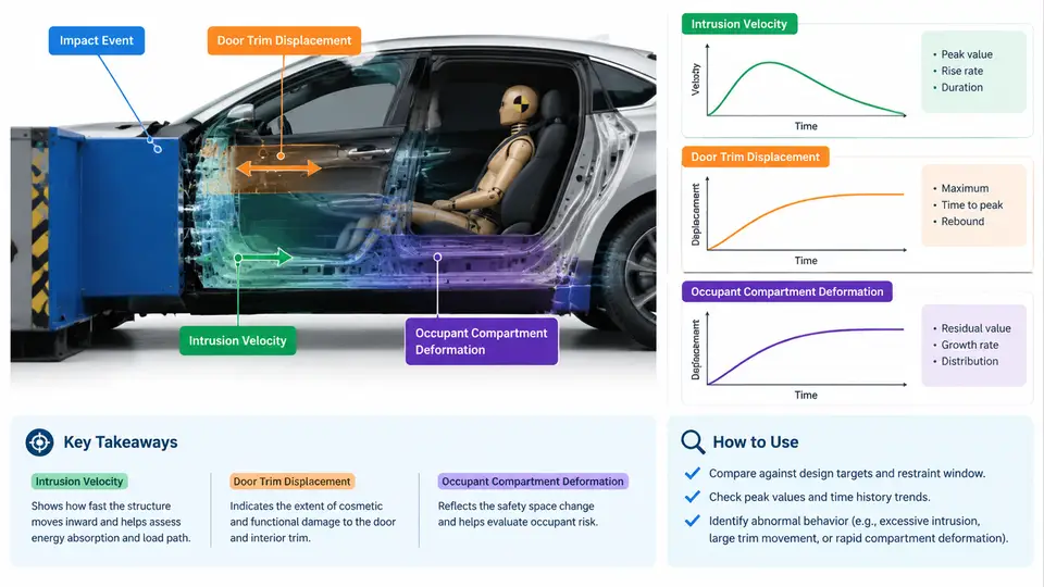
Side impact restraint design begins with a precise description of what the striking vehicle, the struck vehicle, and the occupant actually experience during the collision. Unlike frontal crashes, where the occupant is driven forward into a restraint, a side impact delivers the barrier or bullet vehicle directly into the occupant's seating space. The available crush distance between the door outer panel and the occupant's hip or thorax is often only 150–250 mm, and the entire intrusion event may complete within 40–80 ms. Restraint timing windows — when a side airbag must deploy, how fast the inflator must fill, and how the door trim must behave — are derived directly from the crash pulse and intrusion characteristics. This chapter establishes the measurement framework and the key metrics that feed every downstream timing decision.
Coordinate Convention and Sign Definitions
Before any metric is defined, the reference frame must be fixed. In this course, the vehicle coordinate system follows the ISO 4130 convention: X is longitudinal (positive forward), Y is lateral (positive to the vehicle's right), and Z is vertical (positive upward). For side impact analysis, the critical direction is lateral intrusion, defined as displacement of a structure in the −Y direction for a struck vehicle on its left side (i.e., toward the occupant compartment centerline). Intrusion velocity is therefore the first time derivative of that displacement, expressed as a negative value when the structure moves inward. All figures and tables in this chapter use this convention consistently; when a right-side impact is analyzed, the sign flips but the magnitude definitions remain identical.
The Side Impact Crash Pulse
The crash pulse is the acceleration–time history measured on a non-deforming reference point of the struck vehicle — typically the sill, the tunnel, or a rigidly mounted accelerometer on the struck-side B-pillar base. It is not a single curve but a family of signals: the struck-side sill acceleration, the door inner panel acceleration, the seat frame acceleration, and the occupant compartment acceleration at the outboard seating position. Each serves a different purpose. The sill pulse characterizes the energy input from the bullet vehicle; the door inner panel pulse characterizes what the trim and airbag system must react to; the seat frame pulse defines the occupant's kinematic environment.
A typical side impact pulse from a moving deformable barrier (MDB) test at 50 km/h shows a rapid rise to peak acceleration of 15–25 g within 8–15 ms, followed by a decay over 40–60 ms. The pulse shape is strongly influenced by the bullet vehicle's stiffness, the struck vehicle's side structure (B-pillar, rocker, door beams), and the overlap configuration. For restraint timing, the most important derived quantity is not peak acceleration but the time to intrusion onset — the interval between T0 (first contact) and the moment the door inner panel begins moving inward with meaningful velocity.
Intrusion Velocity
Intrusion velocity is the rate at which the struck-side structure moves into the occupant compartment. It is obtained by integrating the door inner panel or B-pillar accelerometer signal, or more directly by differentiating displacement measured with a high-speed camera or a string potentiometer. In practice, intrusion velocity is reported at specific structural points: the door inner beltline, the armrest, the B-pillar at H-point height, and the rocker at the occupant's hip location.
Typical peak intrusion velocities at the door inner panel range from 4 to 9 m/s for MDB tests at 50 km/h, with the peak occurring 15–30 ms after T0. The velocity profile is more diagnostic than the displacement profile because it reveals the rate at which the occupant's survival space is being consumed. A door that intrudes 200 mm over 60 ms is far less threatening than one that intrudes 120 mm over 20 ms, even though the final displacement is smaller. Restraint designers therefore use intrusion velocity to set the airbag trigger threshold and the required inflation rate.
Door Trim Displacement
Door trim displacement is the movement of the interior trim surface — the armrest, the door card, the bolster — relative to the occupant compartment reference frame. It differs from structural intrusion because the trim can compress, deflect, or separate from the door inner panel before the structure itself yields. This distinction matters for restraint design: the airbag must deploy into the gap between the trim and the occupant, and if the trim is already moving inward at high velocity, the effective gap closes faster than structural intrusion alone would suggest.
Trim displacement is measured with a linear potentiometer or a high-speed camera tracking a target on the armrest and the door card at hip and thorax height. A representative MDB test might show 30–50 mm of trim displacement at the armrest by 25 ms, while structural intrusion at the same height is only 15–25 mm — the difference being trim compression and hinge rotation. The trim velocity during this phase can reach 3–5 m/s, which is a critical input to airbag deployment timing: the airbag must be fully positioned before the trim surface reaches the occupant's hip or thorax.
Occupant Compartment Deformation Metrics
Occupant compartment deformation is characterized by a set of standardized metrics that describe how much the survival space has been reduced and where. The most widely used are:
- Maximum intrusion — the peak inward displacement at a defined structural point (B-pillar, door inner panel, rocker, floor pan), measured relative to the pre-test position.
- Intrusion rate — the time derivative of intrusion, reported as peak velocity and as the average velocity over the first 30 ms.
- Residual intrusion — the permanent deformation remaining after the pulse, which indicates structural yielding and post-crash egress difficulty.
- Compartment volume reduction — the change in the occupant compartment's free volume, often estimated from a small set of intrusion measurements or from a 3D scan of the post-test interior.
- Door opening and latch integrity — whether the door remains closed and latched, which affects occupant retention and post-crash extraction.
These metrics are not independent. A high intrusion rate at the B-pillar typically correlates with large residual intrusion and significant volume reduction, but the relationship is configuration-dependent. The table below summarizes representative ranges from published MDB and pole test data for mid-size passenger cars; these are illustrative values for teaching, not a specification.
| Metric | Measurement Point | Typical Range (50 km/h MDB) | Design Relevance |
|---|---|---|---|
| Peak intrusion velocity | Door inner panel, H-point height | 4–9 m/s | Airbag trigger threshold, inflator sizing |
| Peak intrusion velocity | B-pillar, H-point height | 3–7 m/s | Structural countermeasure timing |
| Trim displacement at 25 ms | Armrest | 30–50 mm | Airbag gap closure, trim design |
| Maximum structural intrusion | Door inner panel | 120–250 mm | Survival space, occupant loading |
| Residual intrusion | B-pillar base | 40–90 mm | Post-crash egress, door latch |
| Compartment volume reduction | Whole compartment | 8–18% | Occupant kinematics, restraint space |
From Pulse to Timing Window
The practical purpose of characterizing the pulse is to define the restraint design window. The window opens when the threat becomes irreversible — typically when intrusion velocity exceeds a threshold such as 2–3 m/s at the door inner panel — and closes when the trim surface reaches the occupant's hip or thorax. The width of this window is the time available for sensing, decision, inflation, and positioning. A pulse with a 25 ms window demands a faster sensing algorithm and a higher-mass-flow inflator than one with a 45 ms window.
The SVG below illustrates the relationship between the crash pulse, intrusion velocity, trim displacement, and the resulting restraint timing window for a representative left-side MDB impact. The upper trace shows sill acceleration; the middle trace shows intrusion velocity at the door inner panel and the trim surface; the lower band shows the timing window bounded by intrusion onset and trim-to-occupant contact.
Practical Measurement Workflow
To produce these metrics from a physical or sled test, the following workflow is used. First, mount accelerometers on the non-deforming sill reference and on the door inner panel at H-point height, filtered to SAE J211 CFC 180 for structural signals and CFC 60 for occupant-relevant signals. Second, place string potentiometers or high-speed camera targets on the armrest and door card to capture trim displacement separately from structural displacement. Third, define T0 as the first frame of barrier contact, confirmed by a contact switch or by the first acceleration excursion above 2 g on the struck-side sill. Fourth, integrate the door inner panel acceleration to obtain velocity, and cross-check against the differentiated displacement signal; a mismatch greater than 10% usually indicates a mounting resonance or a filtering inconsistency. Fifth, extract the timing window by identifying the moment intrusion velocity crosses the trigger threshold and the moment trim displacement reaches the occupant's nominal hip or thorax position.
With the pulse, intrusion velocity, trim displacement, and compartment deformation metrics established, the restraint designer has the quantitative basis for the next step: translating these time histories into sensor thresholds, airbag trigger times, and inflator performance requirements. The timing window derived here is the constraint within which every subsequent restraint decision must fit.