1. Introduction to side impact occupant-to-
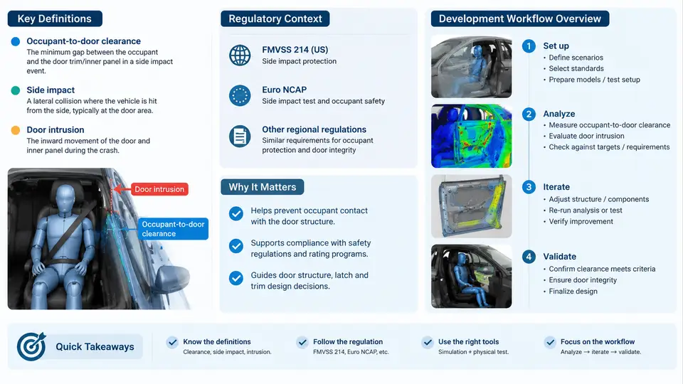
Side impact occupant-to-door clearance is the physical distance between the occupant's body surface and the interior trim of the door (or side structure) at any point during a crash event. It is one of the most consequential packaging dimensions in vehicle body engineering, because side impact offers the occupant almost no crumple zone: the striking vehicle, the door structure, and the occupant's torso occupy the same short lateral span. Clearance is therefore not a comfort metric but a safety-critical design variable that governs how much energy-absorbing structure, padding, and restraint travel can be placed between the occupant and the intruding door surface.
The concept is best understood as a chain of interacting gaps rather than a single number. From the occupant outward, the relevant sequence is: occupant torso surface → seat bolster and trim → armrest and door trim substrate → energy absorber (foam, honeycomb, or molded ribs) → door inner panel → door intrusion beam → door outer panel. Each interface consumes part of the available lateral space, and each has its own tolerance stack-up. When engineers speak of "occupant-to-door clearance," they usually mean the residual gap between the occupant's 50th-percentile or 95th-percentile body surface and the door trim at a defined height and fore-aft station, measured in a specified seating posture. That definition must be fixed early, because a clearance value without a stated posture, station, and percentile is meaningless.
Why clearance matters in side impact
In a side impact, the struck vehicle's door is pushed inward within tens of milliseconds. The occupant, restrained only by the seat and the side airbag, initially stays roughly in place due to inertia, so the effective gap closes rapidly. Clearance determines three things simultaneously: the distance available for the side airbag to deploy and cushion the torso, the amount of door intrusion that can occur before the occupant is contacted, and the space available for energy-absorbing trim to stroke. Insufficient clearance produces a characteristic failure signature — high chest deflection, elevated rib acceleration, and a "bottoming out" of the airbag against the door trim before the occupant's torso has been decelerated. Conversely, excessive clearance can push the occupant outboard into a less favorable restraint geometry and increase the risk of head-to-window or torso-to-B-pillar contact. The design target is therefore a controlled window, not a maximum.
Regulatory and consumer-test context
Clearance development is driven by the test configurations the vehicle must satisfy. The principal references are:
- FMVSS 214 (United States) — dynamic side impact with a moving deformable barrier (MDB) at 90° and a rigid pole test, evaluated with the ES-2re and SID-IIs dummies.
- UN R95 (Europe and many other markets) — MDB side impact at 50 km/h with the ES-2 dummy.
- China GB 20071 — harmonized in structure with R95, with domestic test-lab practice.
- Consumer programs — Euro NCAP and C-NCAP side barrier and pole tests, plus far-side and oblique configurations in newer protocols, which often impose stricter chest and pelvis criteria than regulation.
Each protocol specifies barrier geometry, impact angle, dummy type, seating position, and injury criteria (chest deflection, rib acceleration, abdominal force, pelvis force). Because dummy geometry differs — the ES-2 has a wider, flatter thorax than SID-IIs — the same physical clearance produces different measured deflection. A clearance target validated with one dummy family must be re-checked against the other. This is why clearance is managed as a matrix of dummy × impact configuration × seating position rather than a single scalar.
The development workflow
Clearance development follows a staged workflow that moves from target setting through CAD packaging, CAE prediction, hardware validation, and production control. The figure below shows the workflow and, critically, the feedback loops that make it iterative rather than linear.
In practice, the workflow begins with target setting: the regulatory and consumer criteria are translated into allowable chest deflection, which is then converted into a minimum clearance at each measurement station using dummy-specific compliance data. A typical working assumption for a B-pillar-adjacent station might be a 90–110 mm residual gap at the 50th-percentile torso surface, but this must be derived from the specific dummy and airbag package rather than copied. The CAD packaging stage then checks that the occupant surface, seat, trim, absorber, and door structure fit within that window across the full seat-track travel and recline range, including tolerance stack-up at worst-case build.
CAE prediction uses an explicit dynamic side-impact model (commonly LS-DYNA) with a validated dummy model and a barrier model matching the target protocol. The key outputs are door intrusion versus time at the occupant contact station and the resulting chest deflection. If predicted intrusion at 40–60 ms exceeds the available clearance before airbag cushioning is established, the design is flagged. Hardware testing then confirms the prediction on a sled or full vehicle, and production control ensures that build variation — trim thickness, seat foam density, door seal compression — does not erode the validated margin.
What "good" looks like at the end of this stage
A well-run introduction phase produces three deliverables: a clearance requirement table per station and dummy, a packaging layout showing the gap chain from occupant to door outer, and a CAE-to-test correlation plan. The requirement table should state the target, the minimum acceptable value, and the measurement convention. The packaging layout should identify the tightest station — usually the occupant's thorax at the armrest height, where trim, absorber, and intrusion beam compete for the same space. The correlation plan should define which test will validate which CAE prediction, so that feedback loops in the figure above are scheduled rather than reactive.
With these foundations fixed, subsequent chapters can treat clearance as a quantitative design variable: how to measure it, how to allocate it across the gap chain, how intrusion and airbag deployment interact with it, and how to manage its variation through production. The remainder of this course builds that quantitative capability on the definitions and workflow established here.