1. Rear-facing restraint compatibility engi
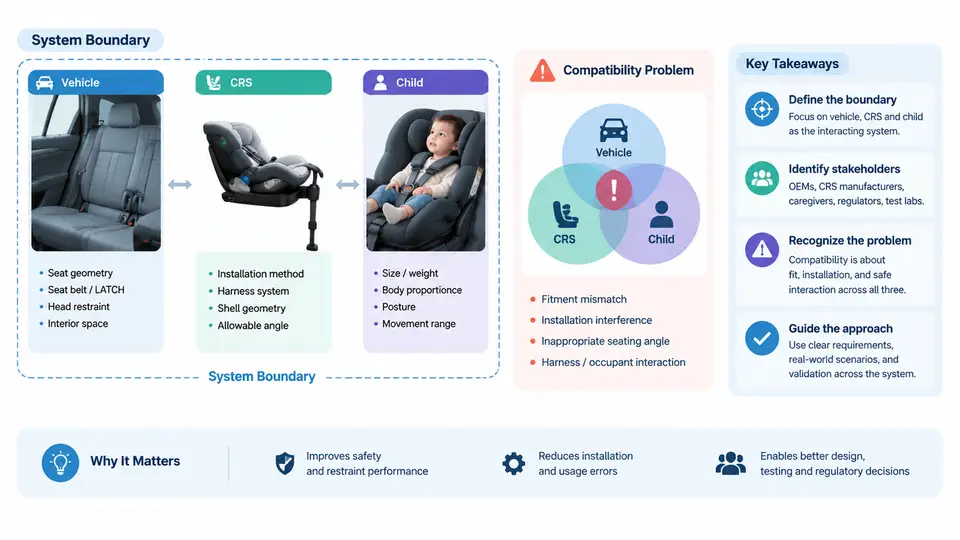
Rear-facing child restraint compatibility is often treated as a single question: "Does this seat fit this car?" In engineering practice, that question is unanswerable until the system under analysis is defined. A rear-facing child restraint system (CRS) is not a standalone product; it is one element of a coupled assembly whose performance emerges from the interaction of three distinct bodies — the vehicle, the restraint, and the child — each with its own geometry, compliance behavior, and loading characteristics. Compatibility engineering begins by drawing a defensible system boundary around that assembly and identifying every stakeholder whose requirements act on it.
Why the Boundary Must Be Drawn First
Consider a common field complaint: a rear-facing infant seat installs with acceptable movement at the belt path on a test bench, but in a specific vehicle the same seat rocks noticeably at the head end. If the system boundary is drawn at the CRS shell alone, the engineer will chase a shell-stiffness problem that does not exist. If the boundary includes the vehicle seat cushion geometry, the belt routing path, and the buckle stalk position, the actual mechanism becomes visible: a deeply contoured cushion holds the CRS base at an angle, the lap belt rides high on the shell, and the resulting moment arm allows rotation about the belt path. The defect lives in the interface, not in either component.
For this course, the system boundary is defined as follows: the rear-facing CRS, the vehicle seating position and its restraint anchorage hardware (seat belt or ISOFIX/LATCH lower anchors and top tether where applicable), the child occupant, and the contact interfaces among all three. Everything outside that boundary — vehicle structure forward of the seat cushion, cargo, other occupants — is treated as environment and enters the analysis only through boundary conditions such as crash pulse and seat-back deflection.
The Three Bodies and Their Coupled Interfaces
Each body contributes a distinct set of variables, and compatibility failures almost always occur at the interfaces between them rather than within a single body.
- Vehicle side: seat cushion angle and contour, cushion compliance, seat-back angle, buckle stalk length and stiffness, lower anchor bar position and depth, anchor bar diameter, and the geometry of the seat bight. These variables determine the CRS installation angle, the belt or connector routing, and the pre-load path into the vehicle seat.
- CRS side: shell and base geometry, belt path height and width, recline adjustment range, harness slot heights, headrest position, and the stiffness of the base-to-shell connection. These determine how the restraint converts anchorage loads into shell motion and how the child is contained.
- Child side: seated height, weight, torso depth, and head position relative to the shell. The child is not a passive payload — the child's dimensions determine harness routing, and the child's mass participates in the coupled dynamics during a crash pulse.
The interfaces are where the engineering problem actually lives. The vehicle–CRS interface governs installation angle and anchorage load path. The CRS–child interface governs containment and harness fit. The vehicle–child interface is indirect but real: vehicle seat contour and CRS recline jointly determine the child's recline angle, which affects airway positioning for infants and head excursion for older rear-facing occupants.
Stakeholders and Their Conflicting Requirements
Compatibility is not a single-requirement problem. Each stakeholder imposes constraints that can pull the design in different directions, and the engineer's job is to find the region where all constraints are simultaneously satisfiable.
| Stakeholder | Primary requirement | Typical conflict |
|---|---|---|
| Child occupant | Containment, correct recline for airway, comfort over trip duration | Deeper recline improves infant airway but increases head excursion in a crash |
| Caregiver / installer | Installation within a defined force and time budget, unambiguous feedback that installation is correct | A tight belt path that reduces movement may be hard to tension by hand |
| Vehicle manufacturer | Anchorage durability, seat cushion integrity, no damage from CRS contact | High pre-load into a soft cushion can cause permanent compression |
| CRS manufacturer | Regulatory compliance across a broad vehicle fleet, shell stiffness targets | Fleet-wide geometry variation forces conservative, sometimes suboptimal, belt path design |
| Regulator / test house | Reproducible pass/fail against defined test benches and dummies | Bench geometry may not represent the worst-case vehicle contour |
The table makes the central engineering tension explicit: the caregiver wants a tight, low-movement installation, while the vehicle manufacturer wants limited cushion compression, and the child's airway requirement may demand a recline angle that increases the moment arm at the belt path. Compatibility engineering is the discipline of quantifying these trade-offs rather than resolving them by intuition.
Framing the Compatibility Problem Quantitatively
A practical way to make the problem tractable is to express compatibility as a set of interface variables with target ranges, then check whether a given vehicle–CRS–child combination falls inside all ranges simultaneously. The following example uses representative, illustrative values — they are teaching assumptions, not measured data.
Interface variable            Target range (example)     Measured / estimated
--------------------------------------------------------------------------
Installation recline angle    30° – 45° from vertical   38°  (in range)
Belt path height above bight  20 – 60 mm                72 mm (OUT of range)
Head-end shell movement       ≤ 25 mm (hand force)      34 mm (OUT of range)
Harness slot vs. shoulder     at or just below shoulder 1 slot below (OK)
Cushion compression (static)  ≤ 15 mm                   11 mm (in range)
--------------------------------------------------------------------------
Diagnosis: belt path rides high on the shell → long moment arm →
excess head-end rotation. Interface problem, not shell-stiffness problem.
The diagnostic value comes from reading the variables together. A high belt path combined with excess head-end movement points to a moment-arm mechanism at the vehicle–CRS interface. The corrective action is therefore geometric — change the recline setting, adjust the base, or select a different seating position — rather than a change to the CRS shell itself. This is the practical payoff of defining the boundary correctly: it directs the fix to the interface where the mechanism actually operates.
What "Compatible" Means Operationally
Within this course, a rear-facing configuration is compatible when three conditions hold at once: the installation achieves a recline angle inside the child-appropriate range, the anchorage load path produces shell movement below the defined threshold under the specified check force, and the harness geometry places the child in a contained posture with correct slot alignment. Each condition is measurable, each has a defined check method, and each can fail independently. The remainder of the course builds the measurement methods, the geometric models, and the corrective procedures that let an engineer move from a field complaint to a verified interface fix.
The first discipline, then, is not calculation but definition: draw the boundary, list the stakeholders, name the interfaces, and express each interface as a variable with a target range. Everything that follows — geometry modeling, anchorage load analysis, child posture assessment, and validation — depends on that initial framing being correct.