1. Course overview
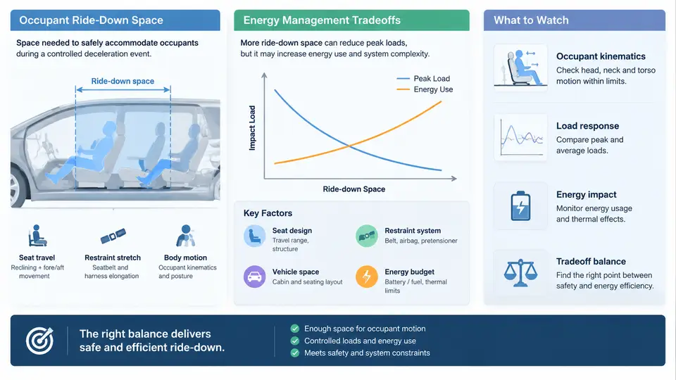
Occupant ride-down space and energy management is the discipline of ensuring that, during a crash event, the vehicle's deformation and restraint systems absorb the occupant's kinetic energy within a controlled distance while preserving a survivable volume around the occupant. The two terms are inseparable: ride-down space is the geometric envelope available for the occupant to decelerate relative to the vehicle interior, and energy management is the structural and restraint strategy that converts crash kinetic energy into controlled deformation, friction, and heat rather than into occupant injury. This chapter establishes the vocabulary, the physical framing, and the engineering context that the remaining 29 chapters build upon.
Why the Two Concepts Must Be Treated Together
A common failure mode in early-stage vehicle architecture is to size the front-end crush zone purely from a structural crashworthiness target, then hand the resulting deceleration pulse to the restraint team. The restraint engineer then discovers that the available ride-down distance is insufficient to keep occupant loads below injury thresholds, and the only remaining lever is a more aggressive airbag or a stiffer belt load limiter — both of which trade chest deflection for head excursion. Treating ride-down space and energy management as a single coupled problem avoids this late-stage conflict.
The governing relationship is straightforward. For an occupant decelerating from an initial velocity v0 to rest over a ride-down distance s at approximately constant deceleration a:
v0² = 2 · a · s        →        a = v0² / (2 · s)

Example (illustrative, not measured data):
  v0 = 56 km/h = 15.56 m/s
  s  = 0.65 m  (occupant ride-down distance)
  a  = 15.56² / (2 × 0.65) ≈ 186 m/s² ≈ 19 g
Doubling the available ride-down distance halves the average deceleration. This quadratic sensitivity is why ride-down space is such a valuable — and such a contested — commodity in vehicle packaging. Every millimetre of occupant travel that can be recovered from the interior layout, seat design, or restraint geometry directly reduces the deceleration the occupant must endure.
The Energy Balance View
At the vehicle level, the crash energy is partitioned between structural deformation, restraint system work, and occupant motion relative to the interior. A useful mental model is a three-stage energy chain:
- Vehicle crush: the front structure deforms, generating a force–displacement characteristic that sets the vehicle deceleration pulse.
- Restraint coupling: belts, airbags, and seats apply forces to the occupant, beginning the occupant's deceleration relative to the vehicle.
- Occupant ride-down: the occupant travels forward relative to the interior while decelerating, consuming the remaining relative kinetic energy within the available clearance.
The critical insight is that the vehicle pulse and the occupant response are not independent. A stiffer front structure produces a shorter, higher-magnitude pulse that demands more ride-down distance from the restraint system; a softer structure spreads the pulse but may intrude into the occupant compartment, reducing the very space the restraint system needs. Energy management is therefore a partitioning problem, not a maximization problem.
Technical Context: Where the Tradeoff Lives
The tradeoff is not confined to the front-end structure. It appears in at least four coupled domains that this course treats in sequence:
| Domain | Ride-down space lever | Energy management lever | Typical conflict |
|---|---|---|---|
| Front structure | Crush length before intrusion | Force–displacement shaping, crash boxes | Short overhang vs. pulse magnitude |
| Restraint system | Belt geometry, pretensioner travel | Load limiter force, airbag venting | Chest deflection vs. head excursion |
| Seat and interior | Seat travel, cushion compliance | Seat energy absorption, anti-submarining | Comfort packaging vs. stroke |
| Occupant packaging | Clearance to knee bolster, IP, steering wheel | Interior trim energy absorption | Styling volume vs. survivable space |
Each row is a place where a millimetre or a kilonewton moves from one column to the other. The course's later chapters examine each domain in depth, but the framing established here — that these are coupled partitions of a single energy budget — is what allows the engineer to reason across them.
Reference Frames and Sign Conventions
Because ride-down analysis mixes vehicle-fixed and occupant-fixed quantities, this course adopts a consistent convention throughout. The vehicle coordinate frame is fixed to the undeformed vehicle body, with the x-axis pointing forward (direction of travel) and the origin at the vehicle centreline at the front bumper reference plane. Occupant displacement is measured positive forward relative to the vehicle interior. Ride-down distance s is the forward travel of the occupant's centre of gravity relative to the interior from the moment of restraint engagement to the point of maximum forward excursion. Deceleration is reported as a positive magnitude in g. Any chapter that switches frames will state the switch explicitly.
What This Course Will and Will Not Cover
The scope is passenger-vehicle frontal and frontal-offset crash loading, with extensions to seat-integrated restraint and interior packaging. It covers the analytical relationships (pulse–space–load), the structural and restraint design levers, the occupant packaging constraints, and the verification methods used to demonstrate that a design meets its targets. It does not attempt to reproduce regulatory test procedures in full, nor does it treat side or rear impact except where they constrain the same space budget. The emphasis throughout is on the engineering reasoning that connects a structural decision to an occupant outcome.
An Illustrative Sizing Exercise
To make the coupling concrete, consider a preliminary sizing exercise. Suppose the packaging team reports that the occupant's centre of gravity can travel 0.60 m forward before contacting the knee bolster and instrument panel, and the restraint team targets a peak occupant deceleration of 25 g. Using the constant-deceleration approximation, the maximum velocity from which the occupant can be brought to rest within that space is:
v0 = sqrt(2 · a · s)
   = sqrt(2 × 25 × 9.81 × 0.60)
   ≈ sqrt(294.3) ≈ 17.2 m/s ≈ 61.7 km/h
If the crash pulse delivers the occupant into the restraint at 15.5 m/s (56 km/h test condition), the margin is modest, and any reduction in available space — say to 0.50 m due to a styling-driven IP push-back — raises the required average deceleration to about 24.5 g, consuming nearly all of the margin. This is the kind of arithmetic that should happen early, before the structure is frozen. The numbers here are illustrative and assume constant deceleration; real pulses are shaped, and later chapters replace this approximation with pulse-integrated methods.
Key Takeaways for the Rest of the Course
- Ride-down space and energy management are a single coupled budget, not two independent workstreams.
- Average occupant deceleration scales with the square of impact velocity and inversely with ride-down distance — small space changes have large load consequences.
- The vehicle pulse and the occupant response are linked through the restraint system; structural and restraint decisions must be evaluated together.
- Consistent reference frames and sign conventions are prerequisites for comparing analyses across teams.
- Early, simple sizing arithmetic exposes whether a packaging concept has enough space margin before detailed design begins.
With this framing in place, the course proceeds to the structural side of the energy budget: how front-end crush characteristics are shaped, how they map to the vehicle deceleration pulse, and how that pulse propagates into the occupant's ride-down problem.