1. Course introduction
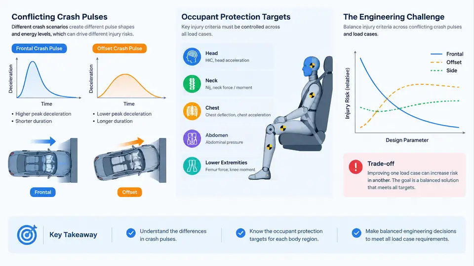
Occupant protection engineering begins with a deceptively simple question: what does "safe" mean for a person inside a vehicle during a crash? The answer is not a single number but a set of injury criteria — quantitative thresholds derived from biomechanics research that describe the likelihood of injury to specific body regions under specific loading conditions. These criteria form the foundation of every restraint design decision, every crash pulse specification, and every regulatory compliance argument. This chapter establishes the vocabulary and the central tension of the course: the same restraint system that protects an occupant in one crash mode can expose that occupant to unacceptable risk in another, because the crash pulses that drive injury mechanisms are fundamentally in conflict.
What Occupant Protection Targets Actually Are
An occupant protection target is a measurable outcome that a restraint system must achieve under a defined test condition. It is expressed as a physical quantity with a threshold and a body region. The most familiar examples come from frontal impact regulation and consumer testing:
- Head Injury Criterion (HIC) — a time-integrated measure of resultant head acceleration, with HIC15 and HIC36 variants depending on the integration window. A common target is HIC15 ≤ 700 for a 50th-percentile male in a 56 km/h frontal barrier test.
- Chest deflection and Viscous Criterion (VC) — chest compression in millimeters and the rate-dependent VC metric, typically targeted at ≤ 50 mm and VC ≤ 1.0 m/s for the same occupant and event.
- Femur axial force — a load-path metric, often ≤ 10 kN per leg, reflecting the tolerance of the femur and the knee-thigh-hip complex.
- Neck injury criteria — Nij (combined tension/compression and bending moment) and neck shear, relevant in both frontal and rear impacts.
These are not arbitrary numbers. Each derives from cadaveric testing, animal models, and epidemiological reconstruction, and each carries an associated injury probability curve. A target of HIC15 ≤ 700 corresponds to a defined — not zero — probability of skull fracture or brain injury. The engineer's job is to manage that probability across a population of occupants and a matrix of crash conditions, not to eliminate injury entirely.
The Crash Pulse as the Forcing Function
The crash pulse is the acceleration-time history experienced by the vehicle structure at the occupant compartment during impact. It is the input to the occupant simulation and the physical driver of every injury metric. A frontal barrier pulse typically rises to 30–50 g within 20–40 ms and decays over 80–120 ms. A rear impact pulse is lower in magnitude but longer in duration. A side impact pulse is short, sharp, and highly localized. Each pulse shape — its peak, its rise time, its duration, its frequency content — determines how the occupant's body loads the restraint system and how the restraint system loads the body.
The critical insight is that restraint systems are tuned to pulses. An airbag inflator sized to cushion a 50 g frontal pulse will deploy too slowly or too aggressively if the pulse changes. A seatbelt load limiter set to pay out at 4 kN to control chest deflection in a frontal crash may allow excessive forward excursion in a different pulse shape. The restraint is a filter between the pulse and the occupant, and its transfer function is only optimal for the pulse it was designed against.
Why the Pulses Conflict
Consider three load cases that a single vehicle must survive: a 56 km/h frontal full-width barrier, a 64 km/h frontal offset deformable barrier (ODB), and a 50 km/h side pole impact. The frontal barrier produces a high-magnitude, relatively uniform deceleration. The ODB produces a lower-magnitude but longer-duration pulse with significant vehicle yaw and intrusion. The side pole produces a short, high-severity lateral pulse with minimal crush space.
The restraint requirements diverge sharply. Frontal protection wants early, firm restraint coupling to keep the occupant in the seat and distribute load across the chest. Side protection wants fast lateral airbag deployment and a stiff structure to prevent intrusion, but the same occupant may be out of position or already displaced by a frontal event. A restraint that is stiff enough for the frontal barrier may be too stiff for the smaller occupant in the ODB, where chest deflection targets are harder to meet because the pulse is longer and the occupant rides down the deceleration for more time. Conversely, a soft, load-limited restraint that protects the small occupant in the ODB may allow excessive head excursion in the frontal barrier, pushing HIC toward its limit.
The Engineering Challenge: Balancing Across the Matrix
The practical work of occupant protection is therefore a multi-objective optimization under uncertainty. The engineer must satisfy HIC, chest, femur, and neck targets simultaneously across a matrix of crash modes, occupant sizes (5th-percentile female through 95th-percentile male), seating positions, and belt-use states. Each cell in that matrix has its own pulse and its own dominant injury mechanism. The restraint system has a limited number of tunable parameters — inflator output, vent size, belt load limiter force, pretensioner timing, anchor geometry — and each parameter moves multiple metrics in different directions.
A useful way to see this is as a parameter-metric sensitivity map. Increasing the belt load limiter force reduces head excursion (good for HIC in the frontal barrier) but increases chest deflection (bad for chest in the ODB). Increasing inflator output reduces head contact with the steering wheel but increases the risk of out-of-position injury and can raise neck loads. There is no setting that improves every metric; the engineer's task is to find the region of parameter space where all metrics remain inside their targets with adequate margin, and to understand which load case is the binding constraint.
Reading the Conflict Map in Practice
The diagram above is the mental model for the entire course. It shows three tunable restraint parameters on the left, three load cases in the middle, and four injury metrics on the right. The red arrows are not failures — they are the sensitivity relationships that make the problem hard. The annotation at the bottom states the binding conflict: the belt load limiter force that minimizes HIC in the frontal barrier is not the force that minimizes chest deflection in the ODB.
In practice, the engineer resolves this by first identifying which load case is binding — that is, which metric reaches its target first as parameters are swept. If the ODB chest deflection is the binding constraint, the load limiter force is set by that case, and the frontal barrier HIC is then verified to retain adequate margin. If the frontal HIC is binding, the reverse applies. The choice of binding case is a program-level decision that depends on regulatory priorities, consumer rating targets, and the vehicle's structural performance.
A concrete example illustrates the workflow. Suppose a baseline calibration uses a 4.0 kN load limiter and achieves HIC15 = 620 and chest deflection = 46 mm in the ODB, both inside target. A program change increases the frontal barrier severity, pushing HIC15 to 740 — outside target. The engineer raises the load limiter to 4.8 kN, which brings HIC15 back to 680 but pushes ODB chest deflection to 54 mm — now outside target. The parameter sweep has revealed the conflict directly. The resolution is not to pick one violation over the other but to change a second parameter: increasing pretensioner force or adjusting anchor geometry to recover chest margin without giving back the HIC gain. This iterative, multi-parameter search is the daily work of restraint calibration.
What This Course Will Build
The remaining chapters develop this framework in depth. You will learn how crash pulses are characterized and compared, how injury criteria are computed from simulation or test data, how restraint parameters map to metrics, and how to structure a calibration campaign that respects the conflict rather than ignoring it. The goal is not to memorize thresholds but to develop the engineering judgment to know which load case is binding, which parameter to move, and when the margin is sufficient. That judgment is what separates a compliant restraint system from a robust one.