1. Head impact contact zones in vehicle int
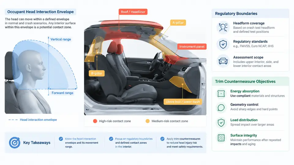
Head impact protection is one of the few interior safety domains where the occupant's own body becomes the test instrument. There is no belt, airbag, or structural crush zone to absorb energy on the occupant's behalf — only the geometry, stiffness, and surface treatment of the trim that the head happens to strike. This chapter establishes the foundational vocabulary for the rest of the course: what the head interaction envelope is, how regulations bound it, and what objectives a trim countermeasure must satisfy.
Defining the Occupant Head Interaction Envelope
The head interaction envelope is the three-dimensional region of the vehicle interior that an occupant's head can plausibly reach and strike during a crash event, projected from a defined seating reference point. It is not a single surface but a swept volume: the head travels along an arc as the torso pivots forward, and the envelope captures every point the head's outer contour can contact along that path.
Two reference constructs anchor the envelope. The H-point (hip point) is the pivot of the seated occupant's torso, established by the seating reference point and the SAE J826 H-point machine. The head center is located relative to the H-point through the head contour defined in FMVSS 201 and ECE R21. From these references, the envelope is generated by sweeping the head form through its forward and lateral travel arcs. In practice, engineers work with a head form — a rigid sphere of 165 mm diameter representing the adult head — and a head impact zone that is the projection of that sphere's reachable volume onto the interior surfaces.
The envelope is bounded by three practical limits. The forward limit is set by the torso pivot arc at maximum forward excursion. The lateral limit is set by the head's side-to-side travel within the seat and by the proximity of side trim. The vertical limit is set by the head's position relative to the roof, header, and upper pillars. Anything inside this envelope is a candidate contact zone; anything outside is not regulated for head impact, though it may still be relevant for other occupant protection modes.
Regulatory Boundaries: FMVSS 201 and ECE R21
Two regulatory frameworks dominate head impact requirements, and they differ in both scope and test method.
FMVSS 201 (Federal Motor Vehicle Safety Standard 201, "Occupant Protection in Interior Impact") applies to passenger cars, multipurpose vehicles, trucks, and buses. It defines target points on the interior — specific labeled locations on the instrument panel, header, pillars, and roof — and requires that a free-motion head form impacting each target at a specified velocity not exceed a Head Injury Criterion (HIC) limit. The current limit is HIC(d) ≤ 1000, where HIC(d) is the HIC value scaled by a dummy-specific factor. The test velocity is typically 24.1 km/h (15 mph) for the free-motion head form, though some target categories use different conditions.
ECE R21 (UN Regulation No. 21, "Interior Fittings") takes a different approach. Rather than enumerating target points, it defines impact zones — geometric regions derived from the head form's reachable envelope — and requires that any fitting within those zones either be removed, be sufficiently soft, or be tested and meet an energy absorption criterion. ECE R21 uses a head form of 165 mm diameter and 6.8 kg mass, impacting at 24.1 km/h, with a deceleration limit expressed as a function of contact duration.
| Parameter | FMVSS 201 | ECE R21 |
|---|---|---|
| Approach | Enumerated target points | Geometric impact zones |
| Head form mass | 4.5 kg (free-motion) | 6.8 kg |
| Head form diameter | 165 mm | 165 mm |
| Impact velocity | 24.1 km/h (typical) | 24.1 km/h |
| Acceptance criterion | HIC(d) ≤ 1000 | Deceleration vs. duration curve |
| Zone definition | Target points on specified surfaces | Reachable envelope from H-point |
The practical consequence of these differences is that a trim component may pass one regulation and fail the other. A European-designed pillar trim optimized for ECE R21's zone-based approach may not cover every FMVSS 201 target point, and vice versa. For vehicles sold in both markets, the design must satisfy the union of both requirements — which usually means the more conservative envelope governs.
From Envelope to Countermeasure Objectives
Once the envelope and regulatory boundaries are established, the trim countermeasure has three objectives, in order of priority.
1. Eliminate or relocate hard contact. The cheapest countermeasure is to move a stiff structure out of the envelope or cover it with compliant trim. A exposed body-in-white bracket inside the head impact zone is a design defect, not a tuning problem. The first pass should always be geometric: can the hard point be moved, recessed, or shielded?
2. Absorb energy within the available package depth. Where a hard structure cannot be relocated, the trim must decelerate the head form within the stroke available. This is a stiffness-matching problem: the trim's force-deflection curve must be shaped so that peak deceleration stays under the limit while the available crush depth is fully used. A trim that is too stiff peaks early and fails; a trim that is too soft bottoms out against the structure behind it and fails late.
3. Maintain function and durability. The countermeasure must still be a production part: it must resist sun load, humidity, and occupant wear without losing its energy-absorbing geometry. A foam pad that passes the lab test but collapses after two summers in a parked car is not a countermeasure.
Worked Example: Mapping a B-Pillar Trim to the Envelope
Consider a mid-size SUV with a B-pillar upper trim panel. The H-point is established at the driver's seat reference point. The head center at the design position is 650 mm above the H-point and 200 mm rearward. The forward travel arc sweeps the head center through a 400 mm radius arc; the lateral travel is ±150 mm. The resulting envelope intersects the B-pillar trim over a vertical band from 150 mm to 450 mm above the H-point.
The engineer overlays the FMVSS 201 target points for the B-pillar onto this band. Suppose three target points fall within the band. The trim's current design is a 2.5 mm polypropylene substrate with a 1 mm foam backing. A preliminary check — using the substrate's flexural modulus and the foam's compressive stress-strain curve — suggests the peak deceleration at the stiffest target will exceed the HIC(d) limit by roughly 15%. The countermeasure options are: increase foam thickness to 3 mm (adds 2 mm package depth, reduces peak by an estimated 20%), add a ribbed energy-absorber behind the substrate (adds 8 mm depth, reduces peak by 35%), or relocate the target point by reshaping the trim surface (no depth cost, but requires a body-in-white change). The first option is selected for the initial design iteration, with the second held as a fallback if the foam alone proves insufficient in physical testing.
Practical Takeaways for the Design Process
Three habits separate teams that pass head impact validation on the first attempt from those that iterate through multiple physical test rounds.
Define the envelope before the hard points. The head interaction envelope should be generated at the concept stage, when the body-in-white and interior package are still fluid. A hard point placed inside the envelope at concept becomes a trim-tuning problem at validation — and trim tuning has far less leverage than geometry.
Treat the two regulations as a union, not a choice. For global programs, the design target is the more conservative of FMVSS 201 and ECE R21. This usually means the ECE R21 zone-based envelope governs the coverage area, while the FMVSS 201 HIC(d) limit governs the acceptance criterion. Document both in the requirement specification.
Validate the force-deflection curve, not just the peak. A trim that passes on peak deceleration but bottoms out against the structure behind it has no margin. The design should show that the available crush depth is used efficiently — the force-deflection curve should rise smoothly to the limit and stay there, not spike and collapse.
The remaining chapters build on this foundation: material selection for energy absorption, geometric design of ribs and foam, test fixture design, and the correlation between lab results and real-world head protection. Every one of those topics assumes the envelope and objectives defined here.