1. Frontal crash modes and restraint system
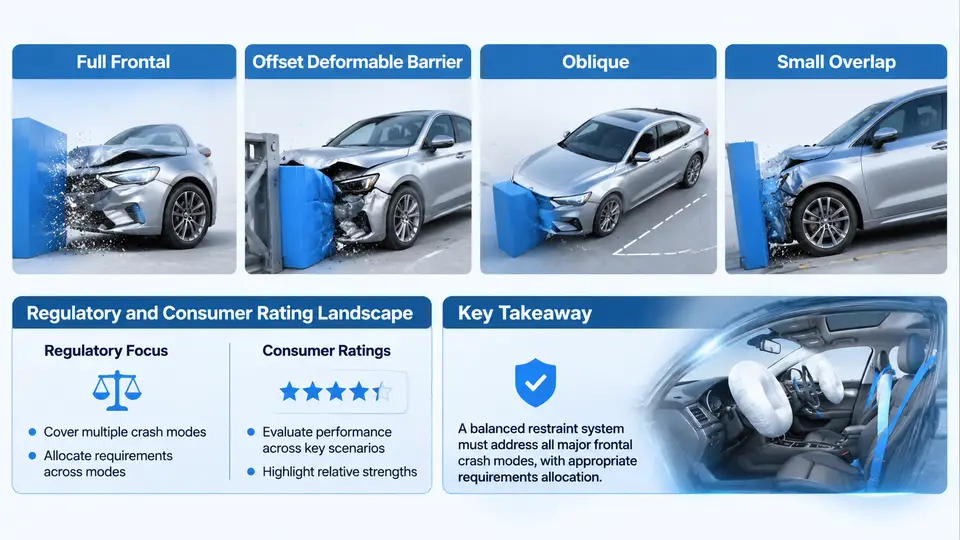
Frontal restraint design is not a single problem with a single answer. A vehicle that performs well against a rigid flat wall may still expose its occupants to severe injury in a narrow offset impact, and a restraint system tuned for a 56 km/h full frontal test can behave very differently at 64 km/h against a deformable barrier. Before any requirement can be allocated to an airbag, a seat belt, a load limiter, or a pretensioner, the engineering team must first define the crash modes the vehicle will be evaluated against, the regulatory and consumer programs that govern each mode, and the physical mechanisms that distinguish one mode from another. This chapter establishes that foundation and explains why requirements allocation is the discipline that connects crash-mode physics to component-level specifications.
The four canonical frontal crash modes
Frontal impacts are conventionally grouped into four modes, each with a distinct load path, occupant kinematics, and restraint demand.
Full frontal impact engages the entire front structure against a rigid or near-rigid barrier. Both longitudinal rails, the cradle, and the firewall participate, so deceleration is high but relatively symmetric. Occupants load both belt and airbag in a well-defined, repeatable manner. Because the barrier is wide, the vehicle's full crush width is available, and the occupant compartment typically retains its shape. The dominant restraint challenge is managing peak deceleration and chest loading rather than structural intrusion.
Offset deformable barrier (ODB) impact, typically 40% overlap against a honeycomb barrier, concentrates load on one side of the vehicle. The struck rail crushes deeply while the opposite rail carries little load, producing yaw and lateral occupant motion. The deformable barrier also introduces a softer, longer-duration pulse than a rigid wall. Restraint systems must therefore handle asymmetric belt loading, increased head lateral excursion, and a pulse that rewards early pretensioner firing and controlled load limiting.
Oblique impact, increasingly represented in consumer protocols, strikes the vehicle at an angle (commonly around 15° from the longitudinal axis) with partial overlap. The oblique vector produces both longitudinal and lateral occupant motion, and the occupant can slide outboard relative to the airbag. This mode is particularly demanding for side-curtain and far-side restraint coverage, and it exposes weaknesses in airbag geometry that a purely frontal test would not reveal.
Small overlap impact, such as the IIHS 25% overlap rigid barrier test at 64 km/h, bypasses the longitudinal rails almost entirely. Load enters through the wheel, suspension, and lower A-pillar, causing significant intrusion into the footwell and occupant compartment. Because the primary crush structures are missed, the pulse is short and severe, and the occupant is often thrown forward and outboard. Restraint countermeasures include outboard airbag geometry, knee bolster design, and structural load-path additions rather than belt tuning alone.
Regulatory and consumer rating landscape
Each crash mode is anchored by one or more evaluation programs, and the requirements they impose differ in both intent and severity. Understanding this landscape is a prerequisite for allocation, because a requirement that originates in a regulation and a requirement that originates in a consumer rating carry different margins, different pass/fail logic, and different consequences for the design.
| Program | Mode | Typical condition | Primary metric |
|---|---|---|---|
| FMVSS 208 | Full frontal (rigid barrier) | 56 km/h, unbelted and belted occupants | Head, chest, femur injury criteria; airbag suppression logic |
| ECE R94 / R137 | Offset deformable barrier | 56 km/h, 40% overlap, ECE honeycomb | Head, chest, abdomen, pelvis criteria |
| US NCAP | Full frontal (rigid barrier) | 56 km/h, belted | Star rating from HIC, chest deflection, femur load |
| Euro NCAP | ODB + full-width + mobile progressive deformable barrier | 50–64 km/h variants | Weighted injury scores, structural assessment |
| IIHS | Small overlap (25%) and moderate overlap (40%) | 64 km/h rigid barrier (small), 64 km/h deformable (moderate) | Intrusion, dummy injury, rating tier |
Two observations matter for allocation. First, the same physical vehicle is evaluated under pulses that differ in duration, magnitude, and direction, so a restraint calibration that satisfies one program can violate another. Second, consumer programs increasingly reward structural performance and out-of-position robustness, which means restraint requirements cannot be met by belt and airbag tuning alone; they interact with body structure, seat design, and even interior trim.
Why requirements allocation is the central discipline
Requirements allocation is the process of translating a system-level crash performance target into verifiable, traceable requirements on individual subsystems and components. In frontal restraint work, the system-level target might be "HIC15 ≤ 700 and chest deflection ≤ 50 mm for the 50th percentile male in the 56 km/h full frontal test." Allocation decomposes that target into contributions from the belt (geometry, retractor force limit, pretensioner stroke), the airbag (volume, venting, tethering, firing time), the seat (energy absorption, recliner strength), and the structure (intrusion limits, pulse shaping).
The allocation is not arbitrary. It is constrained by physics: the occupant's forward excursion is governed by the integrated deceleration the restraint applies, and the chest deflection is governed by the force the belt and airbag impose on the thorax. A useful working relationship is that the restraint force F applied over a stopping distance s must absorb the occupant kinetic energy:
0.5 * m * v^2  ≈  ∫ F ds

where:
  m = occupant mass (e.g., 78 kg for 50th percentile male)
  v = occupant velocity relative to vehicle at restraint engagement
  s = available ride-down distance (belt stretch + airbag compression + seat travel)
For a 56 km/h full frontal pulse, the occupant may reach roughly 15–20 km/h relative to the vehicle at the moment the belt and airbag become effective, depending on pulse shape and pretensioner timing. With a ride-down distance of about 0.25 m, the average restraint force is on the order of several kilonewtons, and the peak force must be limited to keep chest deflection within tolerance. This is why load limiters are specified in the 3–5 kN range for many frontal applications, and why the allocation must reserve part of the ride-down distance for airbag compression rather than belt stretch alone.
From mode definition to allocation inputs
A practical allocation workflow begins with a mode-by-mode requirement matrix. For each mode, the team records the pulse (barrier type, speed, overlap), the occupant population (5th percentile female through 95th percentile male, plus out-of-position cases), the injury criteria and their thresholds, and the structural intrusion limits. The matrix then becomes the input to a contribution analysis: for each criterion, which subsystem dominates, and how much margin does each subsystem need to carry?
Consider a worked example. Suppose the full frontal target is HIC15 ≤ 700 and the current airbag and belt design produces HIC15 = 820 in CAE. The team might allocate the gap as follows: 40 points from earlier pretensioner firing (reducing occupant excursion before airbag contact), 50 points from increased airbag venting (reducing head rebound), and 30 points from a softer load limiter (reducing chest force and thus head rotation). These are not measured results; they are allocation hypotheses to be verified in sled testing. The value of the exercise is that it forces each subsystem owner to accept a quantified share of the gap rather than leaving the shortfall to "restraint tuning" as a whole.
Scope of the restraint system in frontal modes
The restraint system scope for frontal crash modes includes the seat belt assembly (retractor, load limiter, pretensioner, buckle, anchorages), the frontal airbag module (inflator, cushion, vent, tether), the knee bolster or knee airbag, the seat structure and its energy-absorbing features, and the occupant classification and suppression logic that determines deployment. Steering column collapse and pedal release are adjacent systems that interact with restraint performance and must be included in the allocation boundary even if they are owned by other teams.
What lies outside the boundary is equally important. Body structure, door trim, and roof rail are structural or interior systems, but their behavior changes the pulse and the occupant's available space, so the allocation must include interface requirements on them: maximum intrusion at the toe pan, maximum steering column rearward displacement, and minimum survival space at the occupant's chest and head. These interface requirements are the mechanism by which restraint allocation remains physically achievable.
With the modes defined, the programs mapped, and the scope bounded, the next step is to build the requirement matrix that will carry through the rest of this course. The matrix is the working document that turns crash-mode physics into component specifications, and every subsequent allocation decision should be traceable back to a row in that matrix.